


To inspect the discharge valves, remove the valve as described in the “Disassembly” section. Inspect the valves by
snapping the valve disk or lower valve spring away from the valve seat to check for spring tension and mechanical de-
fects. Inspect the sealing surfaces for dirt or other foreign material. Check that the disk or lower valve spring has not
warped (dish shape), as they must be flat for full contact. If a more careful inspection is required, remove the cap
screw(s) holding the valve together. When reassembling the valve, replace valve components in exactly the same po-
sition as before.
Reassemble the valves as described in the “Assembly” section
.
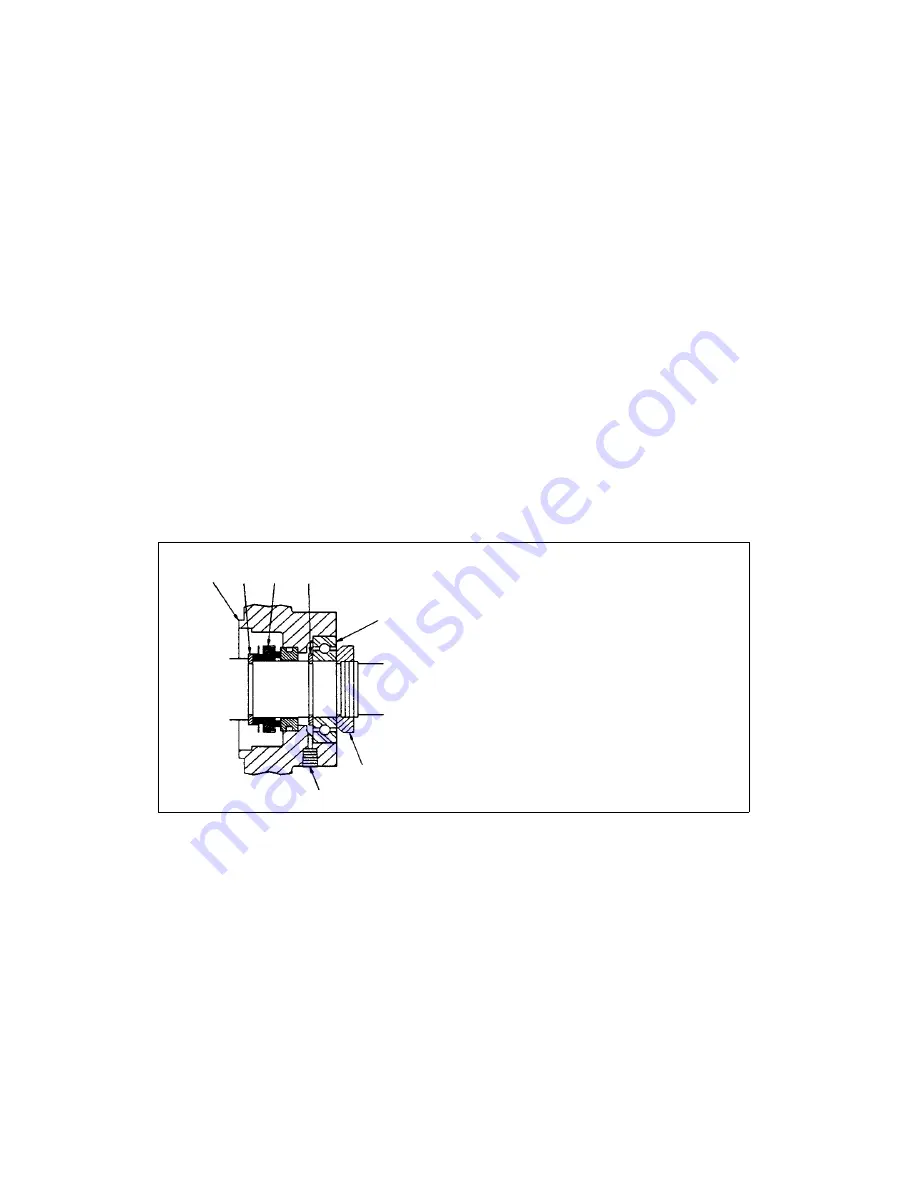
Shaft Seal Assembly
Under normal conditions, the shaft seal (See Figure 4) has a long trouble-free life. It may become worn or scratched
on the sealing face by dirty sealing oil, which also lubricates the shaft seal, or it may be damaged by excessive heat
due to poor lubrication.
If oil drips from the shaft seal and bearing housing, it is an indication that the shaft seal should be inspected and re-
placed as necessary. The drain plug of the shaft seal and bearing housing should be removed as long as oil is leak-
ing past the shaft seal. If oil, which has leaked from the shaft seal, is allowed to drain through the bearing, it will wash
the grease from the bearing and cause it to fail.
To inspect the seal, proceed as follows:
1) Remove the belt guard and belts.
2) Remove the pump pulley and drive key from the shaft.
3) Remove the shaft bearing and housing:
a) Remove the outboard bearing retainer nut from the shaft.
b) Remove the cap screws holding the bearing housing and remove it.
Inspect the face of the running surface for dirt, scratches, or grooves that might cause leaks into the pump. A smooth
shining carbon face indicates a good seal. A crease across the sealing ring, a dent, or scratch in the running face
makes a direct leak through the seal. Cracks or hardening of the rubber parts indicate that the shaft seal was exposed
to excessive operating temperatures and needs to be replaced.
V-Belt Drive
Before attempting to tension the V-belt it is imperative that the sheaves be properly aligned. V-belts should be re-
placed in sets and the sheaves should be positioned so as to allow the belts to be placed in the grooves without roll-
ing them onto the sheaves. The following tensioning steps can be safely followed for all belt types, cross sections,
number of belts per drive, or type of construction.
1) With the belts properly in their grooves adjust the sheaves until all slack has been taken up.
2) Start the drive and continue to tension the V-belt(s) until only a light bow on the slack side of the drive appears
while operating under load conditions as shown in Figure 5.
3) After 24 to 48 hours of operation the belts will seat themselves in the sheave grooves. Further tensioning is then
necessary as described in Step 2.
The belts should not slip if they are correctly adjusted and the correct starting procedure is used. A screeching noise
at start-up may indicate the belts are too loose. Belt dressing should not be used on V-belts. Sheaves and V-belts
14
1
Shaft Seal Bearing Housing
2
Seal Back Up Ring
3
Shaft Seal
4
Bearing Back Up Ring
5
Ball bearing
6
Locknut
7
Drain Plug
1
2
3
4
5
6
7
Figure 4. Shaft Seal Assembly
Summary of Contents for KTC SERIES
Page 18: ...18 KTC 60 KTC 112 Exploded View ...
Page 22: ...22 NOTES ...


