Page 46 of 56
King Pigeon Hi-Tech. Co., Ltd.
Ver 2.3
Industrial Ethernet Remote I/O Module
IoT Data Acquisition Module
10= Write multiple holding registers;
00 00=AO1 register starting address;
00 02 = Control 2 AO;
04=Number of data sent;
00 64 00 C8= The execution data sent is as follows:
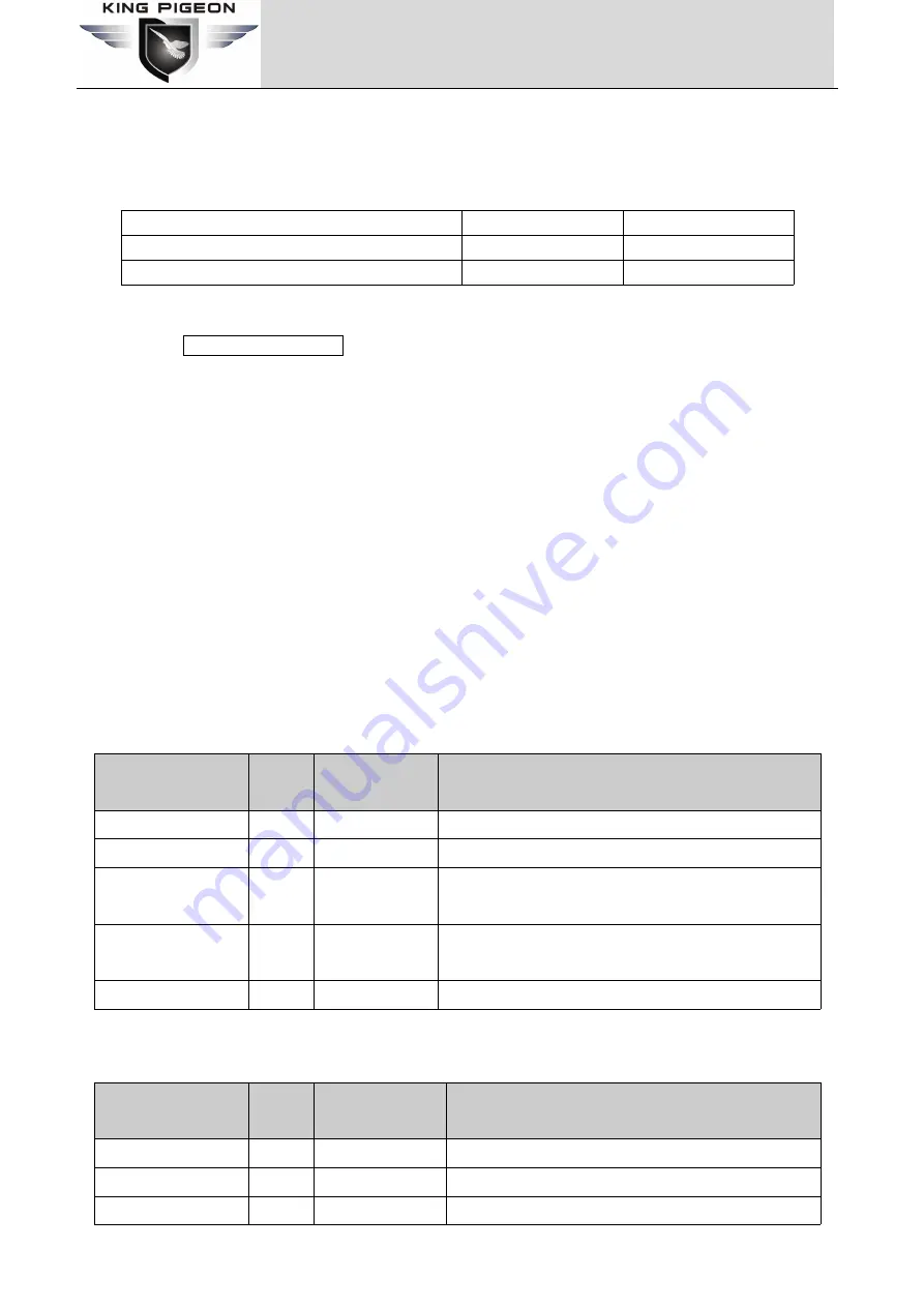
Types
AO1
AO2
Hexadecimal data sent
00 64
00 C8
Converted to true value
100
200
B3 E6 = CRC verify.
Device answer:
01 10 00 00 00 02 41 C8
01= Device address;
10= Write multiple holding registers;
00 00= AO1 register starting address;
00 02 = 2 AO executed data.
41 C8 = CRC verify.
8.3Read device map register
The platform can access the slave device by accessing the mapped address of the local device through the
Modbus protocol. The correspondence between the mapped address and the slave device address needs to be
configured through the Modbus master configuration page.
8.3.1Read Bit mapping address data
Master Send Data Format:
Content
Bytes
Data
(H: HEX)
Description
Device Address
1
01H
01H Device, Range: 1-247, according to setting address
Function Code
1
01H
Read the holding coil, use the function code 01
Bit register starting
address
2
00 64H
Initial addressFor address correspondence, please refer
to the mapping register address
Number of read
registers
2
00 0AH
A total of 300 bit mapping addresses
16 CRC Verify
2
FD D2H
CRC0 CRC1 low byte in front, high behind
Receiver Return Data Format:
Content
Bytes
Data
(H: HEX)
Description
Device Address
1
01H
01H Device, according to the data Master send
Function Code
1
01H
Read hold coil
Return byte length
1
02H
Return Data Length


