ADJUSTMENTS & OPERATION
Mounting or removing chuck or face plate
The 3-jaw chuck comes installed on the lathe, all three jaws move in unison when
adjusted. The supplied 4-jaw chuck has independant jaws and is used for square or
unevenly shaped workpieces. If neither chuck can hold your workpiece, the faceplate
can be mounted using its t-bolts and slots to secure workpiece. The chucks and
faceplate come with a D-6 camlock mount. Before mounting a chuck or face plate, it is
very important that the mounting surfaces on both the spindle nose and the attachment
are extremely clean.
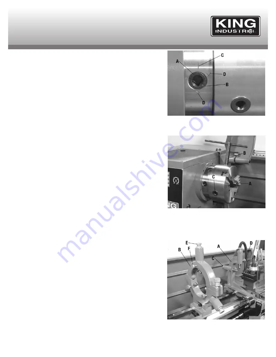
All the camlocks (A) Fig.5 should be in their release position, the camlock mark line (B)
line up with the spindle nose mark line (C). Mount the chuck or faceplate onto the
spindle nose, once in position, each camlock must be tightened and locked into place.
Camlocks (A) are tightened by turning them clockwise using the provided Camlock Key.
The cams are properly locked into place when the camlock mark line (B) is inbetween
the 2 V’s (D) on the spindle nose, see Fig.5.
Adjusting and reversing chuck jaws
Chuck jaws (A) Fig.6 can be opened or closed by using the camlock key (B) in the jaw
adjustment cams (C). Turning the camlock key clockwise will close the jaw opening and
counterclockwise will open the jaw opening.
Before reversing the direction of the chuck jaws, two major points must be followed
every time.
1) The chuck jaws are numbered (ex.: 3 jaw chuck- 1,2,3) and must be placed in
numerical order into the chuck.
2) If the chuck jaws are to be removed, you must replace them in the identical slot which
they were taken out of. (Make sure they are also in numerical order).
To remove chuck jaws, open jaw opening all the way using camlock key until the jaws
practically fall out. Do not let the jaws fall, hold them while you open the jaw opening.
Change the direction of each jaw and apply pressure on them towards the center of the
chuck. Turn camlock key clockwise and make sure all jaws engage the spiral
mechanism.
Installing and operating follow rest and steady rest
The follow and steady rests serve as workpiece supports during operations. Install the
follow rest (A) Fig.7 to the carriage using 2 cap screws. Install the steady rest (B) to the
bedway (inbetween the carriage and the chuck) using the clamp shoe, bolt and lock nut
assembly.
The follow rest is installed near the cutting tool to give additional support. If the follow
rest would not be used, the cutting tool pressure on the workpiece could warp your
workpiece and give undesired results.
Position workpiece in the steady rest and the follow rest. Secure workpiece in rests by
adjusting the position each bearing fingers (refer to knobs C & E) until they all contact
the workpiece. Do not over tighten the bearing fingers. Once adjusted, tighten the lock
knobs (D & F) of each bearing finger.
FIGURE 5
FIGURE 6
FIGURE 7


