OPERATION & ADJUSTMENTS
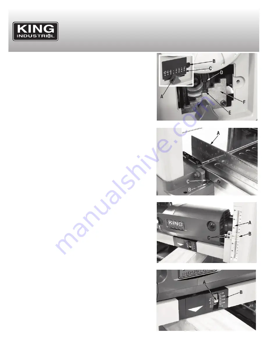
FIGURE 8
FIGURE 9
FIGURE 10
Using and adjusting the pre-set depth stops continued....
The pre-set depth stop Fig.8 is adjusted at the factory, but in some rare cases it
may eventually be necessary to readjust. To adjust the pre-set depth stops:
1. Set the pre-set depth stop to the 1” position by sliding the knob (A) Fig.8.
2. Plane a board thicker than the pre-set depth stop value until the stop prevents
you from lowering the cutterhead.
3. Measure the thickness of the board. If the thickness of the board does not match
the value indicated by the pre-set depth stop, an adjustment is needed.
4. Remove the flat head allen screw (B) Fig.8 with the supplied 4 mm hex. key,
then pull and slide the cover (C) downwards to remove it.
5. Loosen the hex. nut (D) Fig.8.
6. Turn the stop bolt (E) Fig.8 a 1/4” turn in the required direction in order to re-ad-
just the stop bolt against the stop plate (F), retighten the hex. nut (D).
7. Once the adjustment is finished, re-install the cover (C).
Alignment of infeed and outfeed extension tables
1. Place a straight edge (A) Fig.9 across the infeed table and the main table and
make sure that the two tables are aligned. If the tables are not aligned, an ad-
justment is needed.
2. Loosen hex. nut (B) on one side of the infeed table.
3. Turn hex. bolt (C) until the infeed table is aligned with the main table.
4. Retighten hex. nut (B), repeat steps 1 to 4 on the opposite side and then proceed
to verifying if the outfeed table requires adjustment. The adjustment of the out-
feed table is identical to the infeed table.
Adjusting the thickness scale
1. Plane a board and measure its thickness to verify that is the same as the value
indicated by the thickness scale (A) Fig.10 and pointer (B). If the value indicated
is not the same, an adjustement is needed.
2. Loosen pan head screws (C) Fig.10 with a screwdriver, then set the pointer (B)
on the scale so that it indicates the correct thickness. Retighten screws (C) once
the adjustment is completed.
Depth of cut indicator
The depth of cut indicator (A) Fig.11 and scale (B), will indicate how much material
the cutterhead is set to remove from the workpiece for a given pass.
The pointer will read zero until the workpiece engages the front of the cutterhead.
Place the workpiece under the front of the cutterhead and turn the height adjust-
ment handwheel clockwise until the cutterhead makes contact with the workpiece
and until the depth of cut indicator shows the reading that matches the desired cut.
Note:
Failure to follow these recommendations will lead to premature blade wear
and may cause premature motor failure.
It is recommended that for both hard and soft wood:
For stock up to 6” in width, never remove more than
1/8”
per pass.
For stock of 6”-13” in width, never remove more than
1/16”
per pass.
Removing less material per pass and taking multiple passes is always preferred to
more aggressive planing. Advantages include prolonged life of the cutter inserts,
better finish quality (resulting in less time sanding later) and less likelihood of re-
moving too much material causing the workpiece to be too thin for its intended use.
FIGURE 11


