TURNING JOINTER ON & OFF
The On/Off switch is conveniently located on a post, behind the jointer fence, for
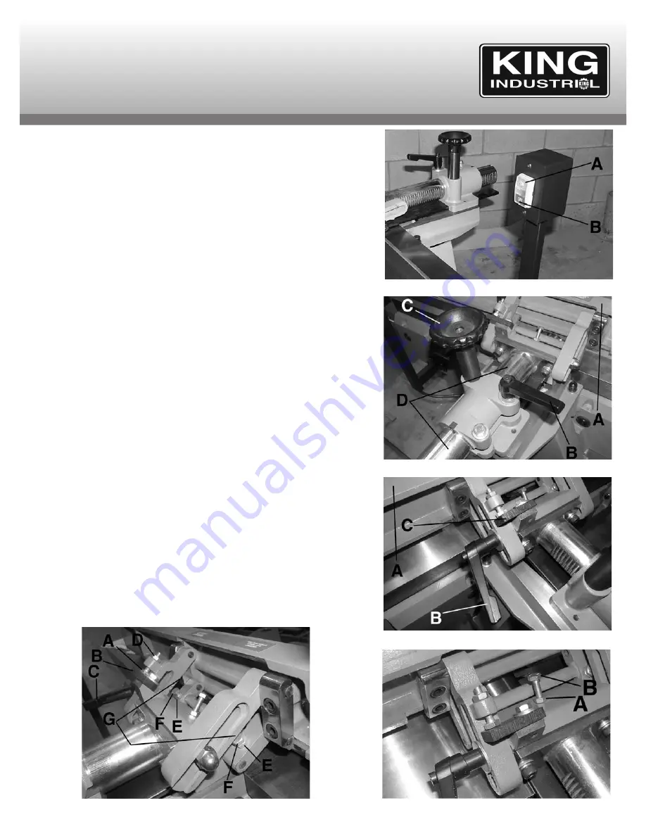
easy accessibility. To start the jointer, press the start button (A) Fig. 7, and to stop
the jointer, press the stop button (B).
FENCE OPERATION
Moving fence forward or backward
The fence (A) Fig. 8, can be positioned anywhere across the table by loosening
lock lever (B) and rotating handwheel (C). Once the fence is moved to its desired
position, retighten lock lever (B) securely. As the fence (A) is moved across the
table, the sliding portion of the column (D) protects you from the cutterhead
during operations.
Tilting the fence
To tilt the fence (A) Fig.9 to the right or to the left, loosen lock handle (B), move
the fence to the desired angle and tighten lock handle (B) securely.
NOTE: When tilting the fence to the right (outward), the stop plate (C) must be
rotated to the up position in order to allow the fence to go past it.
IMPORTANT:
When cutting a bevel, it is recommended whenever possible to tilt
the fence towards the table. The fence will then form a V-shape with the tables,
and the work is easily pressed into the pocket while passing it across the knives.
Adjusting fence positive stops
The fence on your jointer is equipped with positive stops at the most common
fence positions (90º & 45º right and left). To check and adjust the positive stops,
proceed as follows:
1. Position the fence 90º to the table making sure tip of stop bolt (A) Fig.10 is
against stop plate (B). Then tighten lock handle (C).
2. Using a square, check to see if the fence is at 90º to the table.
3. If the fence is not at 90º to the table, loosen lock handle (C) and lock nut (D).
Turn stop bolt until its tip contacts the stop plate (B), tighten lock handle (C).
4. Tilt the fence inward as far as possible and using a combination square(45º),
check to see if the fence is tilted inward 45º to the table. If an adjustment is
necessary, loosen nuts (E) and adjust bolts (F) until tips of bolts (F) contact
brackets (G).
5. Tilt the fence outward as far as possible and using a combination square (45º),
check to see if the fence is tilted outward 45º to the table. NOTE: 90º stop plate
(B-Fig.10) must be rotated up in order to tilt the fence outward. If an adjustment
is necessary, loosen lock nut (A) Fig. 11, and adjust bolt (B) until head of bolt
(B) contacts back of fence.
FIGURE 7
OPERATING CONTROLS
& ADJUSTMENTS
FIGURE 8
FIGURE 9
FIGURE 11
FIGURE 10


