1
EN
QUICK GUIDE:
CAUTION! - Do not install the boom gate without ha-
ving read all the instructions!
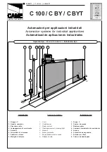
Install the boom gate, the control (key selector switch or push but-
ton panel) and safety devices (emergency stop, photoelectric cells,
sensitive edges and flashing lights) after which do the wiring fol
-
lowing the diagram
fig. 1
.
01.
Prior to turning power on check that the bar is well balanced,
adjusting the balancing spring if necessary.
02.
Release the boom gate using the special spanner and check that
the bar can move without any effort for the whole length of travel.
03.
Power the unit and check that on terminals
1-2
voltage is 230
V AC and on terminals
5-6
it is 24 V d.c.; the LEDs on the active
inputs must turn on and the
OK
LED must flash at a frequency of
1 flash/second.
04.
Check correspondence of the two
FCA
and
FCC
LEDs: when
the bar is closed only the
FCC
LED should turn off and when it is
open only the FCA should turn off.
05.
To exploit the slowing down function it is necessary that the
limit switch triggers about 20° before the actual stopping point is
reached; if necessary adjust the two cams until the limit switch
triggers at the point required.
06.
Check that all the function switches are in the “
OFF
” position.
This means it is in the manual functioning mode, that is, with the
button pressed. Lock the boom gate with the bar at a 45° angle
so it can move freely in both directions. Now give a brief command
pulse on the OPEN input and if the bar does not move in the ope-
ning direction proceed as follows:
a)
Turn the electricity off to the boom gate
b)
Unplug the “
MOTOR
” connector and replug it after it has
been turned 180°
c)
Unplug the “
LIMIT SWITCH
” connector and replug it after it
has been turned 180°
07.
See if rotation direction is right, repeating the procedure de-
scribed above.
08.
Temporarily adjust the
STOP_AMPERE
and
WORKING
FORCE
trimmer to the maximum of the travel,
PAUSE TIME
to
minimum and
SLOWING DOWN FORCE
to halfway travel. Now
try and carry out a complete manoeuvre until the limit switch is
reached and the subsequent stopping point and then try the ma
-
noeuvre in the opposite order.
09.
Set the FUNCTIONS dip-switches as required:
Switches 1-2:
Off Off
=
“Manual” movement (Man Present)
On Off
=
“Semiautomatic” movement
Off On
=
“Automatic” movement (Automatic Closing)
On On
=
“Aut Always Closes” movement
Switches 3
:
On
=
Condominium function
Switches 4
:
On
=
Cancels STOP in the Step-by-Step cycle
Switches 5
:
On
=
Pre-flashing
Switches 6
:
On
=
Flashing also in Pause
Switches 7
:
On
=
Recloses straight after Photocell
(only if on Automatic)
Switches 8
:
On
=
Safety (Photocell) also in opening
Switches 9
:
On
=
Bar open indicator becomes traffic light in
the “one-way” mode
Switches 10
:
On
=
Functioning in the “Traffic light in both di
-
rections” mode
10.
Adjust the two trimmers
WORKING FORCE
and
SLOWING
DOWN FORCE
until obtaining the force and speed required du
-
ring, respectively, the travelling and slowing down phases; only now
adjust the
STOP_AMPERE
trimmer until the triggering threshold
required is obtained.
If in the automatic functioning mode, adjust the PAUSE TIME
trimmer as wanted.
24 VDC
max 200 mA
- (0 v)
FCA
LIMIT SWITCH
FCC
1
2
3
4
+
-
MOTOR
OK
PAUSE
TIME
SLOWING
DOWN
FORCE
WORKING
FORCE
FUNCTIONS
STOP
AMPERE
14
8
6
5
+ (24v)
7
9
10
11
12
13
41
43
42
44
15
CLOSE
OPEN
STEP BY STEP
PHOTO2
PHOTO
STOP
230 VAC
50-60 Hz
LUCY 24 VDC
max 25 W
OPEN (TIMER)
STOP
PHOTO
PHOTO2
STEP BY STEP
COMMON
BAR OPEN INDICATOR
COURTESY LIGHT
AERIAL
2¯ Ch
RADIO
CLOSE
1


