ASSEMBLY
UNPACKING, ASSEMBLY & SET UP
Caution: Follow all of the assembly & installation instructions
completely before connecting the tile saw to a power source or turning
the motor on.
Carefully open the main box and remove all the saw components and packing
materials. Be certain you have checked each item with the parts diagram
before discarding the container or packing materials.
Your 10” sliding tile saw is almost completely assembled, it is necessary to
install the blade guard, pump assembly, blade and guides (if needed for the
operation).
UNFOLDING & LOCKING FOLDING STAND
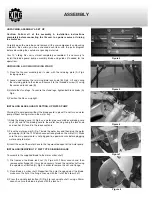
1) Place the tile saw assembly on its side, with the retaining plate (A) Fig.4
facing upwards.
2) Loosen and remove the retaining plate lock knob (B) Fig.4. Lift and swing
the retaining plate to the side and secure it to the threaded screw (C) using
the removed lock knob (B).
3) Unfold the stand legs. To secure the stand legs, tighten both lock knobs (A)
Fig.5.
4) Position the tile saw upright.
INSTALLING BLADE GUARD/ SETTING UP WATER PUMP
Warning! Do not operate without the blade guard in place! Do not turn on water
pump without having water in the water tray.
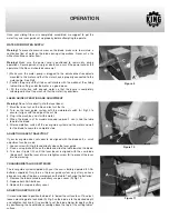
1) Slide the blade guard (A) Fig.6 and water pipe assembly over blade guard
shaft (B) and fix the blade guard to the motor housing using the lock knob
and washer (C) found in the loose contents.
2) Place the water pump (A) Fig.7 inside the water tray and then plug the water
pump plug (B) to the 120V quick-connect receptacle on the motor (C). Make
sure the main power cord is not plugged to a power source before plugging
water pump to motor.
3) Insert the end of the water hose to the top mounted spout of the water pump.
INSTALLING/REMOVING 10” WET TYPE DIAMOND BLADE
To assemble the supplied blade to the motor arbor shaft;
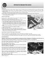
1) First remove the blade lock nut (A) Fig.8 with 23mm wrench and then
remove outer flange (B), it may be necessary to lock the spindle shaft using
the spindle shaft button (D) Fig.3 in order to remove the nut and flange.
2) Place blade on arbor shaft. Reposition the outer flange against the blade,
make sure the flat of the flange lines up with the flat of the arbor shaft.
3) Press the spindle lock button (D) Fig.3 to lock spindle shaft, using a 23mm
wrench, secure the blade in place with the lock nut.
Figure 6
Figure 7
Figure 8
Figure 4
Figure 5


