


ASSEMBLY & OPERATION
INSTALLING GRINDING WHEEL & HANDLE
1) Press and hold down the spindle lock button (A)
Fig.1.
2) Remove the outer flange (B) Fig.1 with spanner
key (A) Fig.2 by turning counterclockwise.
3) Install 7/8” inner diameter grinding wheel (C)
Fig.1 against the inner flange (D).
4) Secure new grinding wheel with outer flange (B)
by pressing and holding spindle lock button and
using spanner key (A) Fig.2 to fix into place
(clockwise).
5) Install the handle on either side or on top of the
motor housing, based on the application or if you
are right or left handed.
6) If the safety guard (E) Fig.1 is not in the most
suitable position for the operation, it is
recommended to shift the position of the safety
guard by removing fixing screws (F), shift safety
guard position and secure with fixing screws.
Warning! If you wish to install a wire brush, the
safety guard must be removed. Reinstall safety
guard once the wire brush operation is finished.
OPERATION
1) To turn the power on, firmly hold the angle
grinder with one hand. Use the other hand to
hold the side handle. Press the on/off trigger (A)
Fig.3 to start the angle grinder.
2) This angle grinder is equipped with a “Trigger
Lock-On” button which is convenient when
continuous operation for extended periods of
time is required. For continuous operation, press
down the trigger switch (A) Fig.3 and push the
“Trigger Lock-on” button (B) located on the side of the handle, then release the trigger.
The tool will continue running after the release of the “Lock-on” button. To stop the tool,
press then release the trigger switch.
3) Use the side handle to help steady the tool and assist movement.
4) Different grinding angles produce different finishes. For rough stock, grind at a 30º
angle. For finishing operations, grind at a 15º angle.
5) Do not use excessive force, let the grinding wheel do most of the work.
6) Once the grinding operation is finished, release the trigger to stop the grinder, wait until
the grinding wheel has come to a complete stop before you put the tool down.
FIGURE 1
FIGURE 3
FIGURE 2
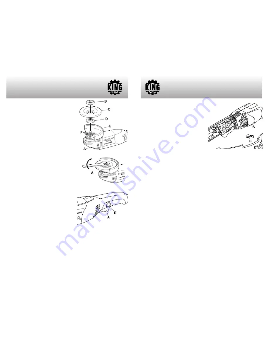
INSPECTING/REPLACING CARBON BRUSHES
Warning! Only use identical replacement carbon
brushes, both carbon brushes should be
replaced at the same time, normally after 50
hours of operation.
Remove 4 screws which secure the two sides of
the tool’s handle together. Separate the two
handles to gain access to the carbon brush
holders (A) Fig.4 (one on each side). Take out
the carbon brushes (B) and inspect them. If the
wear of the carbon brushes has gone past the
limit mark, install new brushes. Reinstall all parts
in reverse order.
FREQUENT INSPECTION AND MAINTENANCE
The tool should be inspected and maintained frequently. Check and make sure the power
cord, internal wires, plug and switch are in good condition. Make sure the insulation
resistance is within normal limits, contact between the brushes and the commutator are
good, and that there is no short-circuit or breakage of the armature and stator windings.
Check the grinding wheel, bearings and driving parts also.
Do not allow brake fluid, gasoline, petroleum-based products such as penetrating oils to
come in contact with plastic parts. They contain chemicals which can damage, weaken or
destroy the motor housing, thus compromising the intergrity of the double insulation.
Inspect mounting screws regularly, making sure they are properly tightened. Tighten all
loose screws before operating.
Service should be done by a qualified service technician using identical replacement parts.
PARTS DIAGRAM & PARTS LISTS
Refer to the Parts section of the King Canada web site for the most updated parts diagram
and parts list.
INSPECTION & MAINTENANCE
FIGURE 4


