12
No.
Name
Description
1
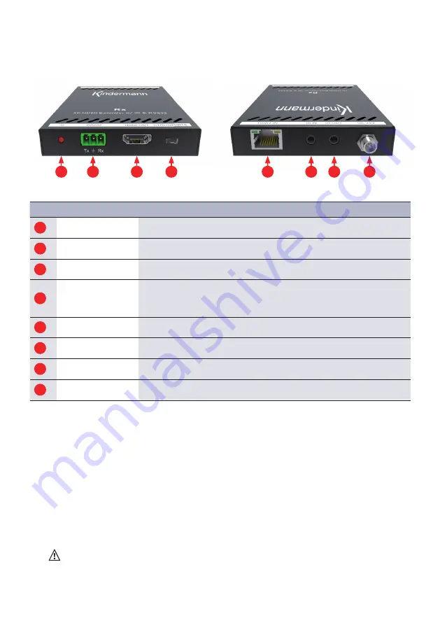
Power LED
Lights red when voltage is applied
2
RS232
Euroblock/Phoenix socket for sending / receiving commands
3
HDMI OUT
HDMI connector for connecting an output device (e. g. display / projector)
4
CTRL/UPDATE
Switch to defi ne the RS232 connection
• In the
CTRL
position, it serves as RS232 transmitter / receiver
• In the
UPDATE
position you can update the operating system
5
HDBT IN
RJ45 jack for connecting the CAT-6/CAT-7 cable from the sender
6
IR IN
3.5 mm jack socket for IR receiver (receiver not included)
7
IR OUT
3.5 mm jack socket for IR transmitter (transmitter not included)
8
DC 24V
DC connector for connecting the optional power supply
5. Operating and display components
1
5
6
7
8
3
4
2
Front side
Rear side
6. Installation
1.
Install the transmitter at the HDMI source (e. g. Blu-ray DVD) and the receiver at the presentation
device (e. g. display / projector).
2.
Connect both units with a single Cat5e/Cat6 cable. Please use a point to point connection, if possible.
3.
Connect the units with the transmitter and receiver via HDMI cable and, if needed, RS232/IR.
4. If needed, connect IR emitters from the IR OUT ports (same with the IR receiver to the IR-In) of
transmitter and receiver and fi rmly attach the IR emitter eye directly over the infrared receiving
sensors of the source and display device to be controlled. Location of the emitter eye on each
device may need to be adjusted later to achieve best IR performance.
Connect the power supply to the transmitter or receiver and power on all devices.
Note:
The maximum range can only be reached by the use of high quality cables and straight
cable runs with no electrical interference and without intermittend connectors.
We recommend to use CAT-6/CAT-7 installation cable with AWG 23 wires.


