103
Chapter 9 Communication
A
CD2S
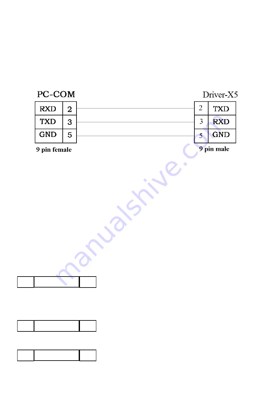
servo driver has the RS232 communication interface, which directly controls the working of the
servo driver with the operation software of a host computer. If the servo driver needs to communicate with a
Programmable Logic Controller (PLC) or other controllers via the free RS485 communication interface,
an
RS232 to RS485 converter
should be added on the driver side.
Fig. 9-1 Communication cables between a PC and a
CD2S
servo driver
9.1 Transport Protocol
The RS-232C communication of the
CD2S
servo driver strictly follows a master/slave protocol. The host
computer can send any data to
CD2S
driver. The driver configured with ID No. will calculate such data and
return a reply. Default communication settings for the
CD2S
servo driver are as follows:
Baud rate = 38400 bps
Data bits = 8
Stop bits = 1
No parity check
The baud rate can be changed by setting d5.02, after changing the value, it is necessary to set d2.00 or d3.00
to save it and reboot the system so that it will take effect.
The transport protocol used by the RS-232 uses a data packet with fixed length of 10 bytes.
ID
CHKS
8 byte data
byte 0
byte 9
ID is the ID No. of the slave
CHKS =-
SUM(byte0,…,byte8), CHKS is the last two digits of the calculation result.
The host sends:
ID
CHKS
8 byte host data
byte 0
byte 9
The slave sends/The host receives:
ID
CHKS
8 byte slave data
byte 0
byte 9
Summary of Contents for CD2S Series
Page 7: ...7...
Page 8: ...8 1 3 3 Power Brake and Encoder cable of Motors...
Page 12: ...12 Fig 2 3 Installation direction...
Page 15: ...15 3 1 2 Wiring Diagram Fig 3 1 Wiring diagram of CD2S driver...
Page 23: ...23 Fig 4 3 Separate regulation of bits...
Page 82: ...82...
Page 96: ...96 8 4 Debugging example 8 4 1 Oscilloscope 1 Enter oscilloscope 2 Parameters for Oscilloscope...
Page 98: ...98 In Auto Reverse mode Kvp 110...
Page 100: ...100 The oscilloscope is as following max following error is 69 inc Fig 2 Kpp 30 Vff 100...
Page 101: ...101 The oscilloscope is as following max following error is 53 inc Fig 3 Kpp 30 Vff 50...
Page 102: ...102 The oscilloscope is as following max following error is 230 inc...


