


www.kimray.com
Page 2
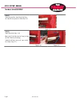
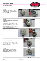
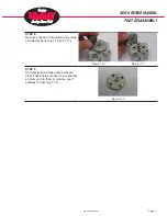
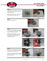
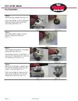
GEN II REPAIR MANUAL
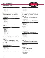
ELASTOMER MATERIALS
TEMPERATURE:
-10° to +350° F
-23° to +177° C
APPLICATION:
Crude Oil & Gas Production, Glycol Dehydrators,
Gasoline, Jet Fuel & Diesel Fuel Pumping, Water Disposal,
Methanol Injection Pumps. (Also Vacuum Service) (Gas
permeability is very low)
FLUID / GAS:
Crude Oil & Gas, Sour Gas (C02), Propane, Gasoline,
Diesel, Fuel Oil Systems
DO NOT USE WITH:
Hot Water, Not preferred for wet H2S, Methyl Alcohol,
Amines, Sodium hydroxide solutions
TEMPERATURE:
-65° to +300° F
-54° to +148° C
APPLICATION:
Steam Flood
FLUID / GAS:
Steam, Water, Alcohol
DO NOT USE WITH:
Crude Oil & Gas, Diester Lubricants (Lube Oils)
TEMPERATURE:
-40° to +220° F
-40° to +104° C
APPLICATION:
High abrasion resistance Seats, Diaphragms
FLUID / GAS:
Crude Oil gas and Water, Sour Gas (C02), propane,
butane, fuel, mineral oil and grease
TEMPERATURE:
±0° to +300° F
-17° to +149° C
APPLICATION:
Production Heaters, Thermostats
FLUID / GAS:
Crude Oil & Gas at High Temperature
DO NOT USE WITH:
Alcohol, Glycols
TEMPERATURE:
-25° to +500° F
-30° to +260° C
APPLICATION:
Crude Oil & Gas Production (High heat), Steam
Flood Production Chemicals (corrosion inhibitors) Amine
Sweetener Systems, Gasoline, Diesel, Fuel Oil Systems
FLUID / GAS:
Crude Oil & Gas Production, H2S, Steam, Petroleum
fluids, Sea Water
TEMPERATURE:
-15° to +300° F
-26° to +149° C
APPLICATION:
Crude Oil & Gas Production w/ H2S C02
FLUID / GAS:
Crude Oil & Gas H2S, C02, Sea Water
TEMPERATURE:
Buna-N:
-40° to +220° F
-40° to +105° C
Low-Temp:
-85° to +120° F
-65° to +49° C
APPLICATION:
Crude Oil & Gas Production Glycol Dehydrators,
Gasoline, Jet Fuel & Diesel Fuel Pumping, Water Disposal,
Methanol Injection Pumps, Water pump seals, hydraulic
pump seals
FLUID / GAS:
Crude Oil & Gas, Good to Poor in Sour Production (See
HSN), Water, Glycols, Hydraulic Oils, Resistance to crude
oil in the presence of hydrogen sulfide and amines, Diesel
fuel, fuel oils
DO NOT USE WITH:
Aromatic hydrocarbons, chlorinated hydrocarbons,
phosphate esters (hydraulic fluids)
TEMPERATURE:
-350° to +500° F
APPLICATION:
High heat, high chemical resistance, highly resistance
to gas permeation
AFLAS
®
is a trade mark of Asahi Glass Co
VITON
®
is a trade mark of Dupont
ETHYLENE PROPYLENE
POLYURETHANE
GYLON
POLYACRYLATE
HSN (Highly Saturated Nitrile)
NITRILE
Summary of Contents for GEN II
Page 1: ...GEN II Repair Manual...
Page 8: ...www kimray com Page 6 GEN II REPAIR MANUAL NOTES...
Page 14: ...www kimray com Page 12 GEN II REPAIR MANUAL NOTES...
Page 18: ...www kimray com Page 16 GEN II REPAIR MANUAL NOTES...
Page 21: ...www kimray com GEN II REPAIR MANUAL NOTES...
Page 22: ......