© 2017 United Technologies Corporation
1 / 2
P/N 3102533-
EN • REV 001 • ISS 15AUG17
KIR-PHD Intelligent
Multisensor Photo-Heat
Detector Installation Sheet
Description
The model KIR-PHD Intelligent Multisensor Photo-Heat Detector is an
intelligent device that contains a photoelectric smoke sensor and a
rate-of-rise heat sensor with a fixed temperature setting. The detector
analyzes the data from both sensing devices and determines whether
an alarm should be initiated. Can be operated as a single detector
using smoke or heat to initiate an alarm.
LED indicator.
The LED indicator (see Figure 2) displays the following
states:
•
Normal: Green LED indicator flashes, no action.
•
Alarm/active: Red LED indicator flashes, evacuate the area.
Installation
Notes
•
This detector does not operate without electrical power. As fires
frequently cause power interruption, discuss further safeguards
with the local fire protection specialist.
•
This detector does not sense fires in areas where smoke or heat
cannot reach the detector. Smoke or heat from fires in walls, roofs,
or on the opposite side of closed doors may not reach the detector.
•
Photoelectric detectors have a wide range of sensing capabilities,
and are best suited for detecting slow, smoldering fires. The heat
sensor in this device provides a source of supplemental
information. The heat sensor by itself does not provide life safety
protection.
•
To ensure proper operation, store the detector within the
recommended ranges. Allow the detector to stabilize to room
temperature before applying power.
•
The dust cover (supplied) must remain on the detector during
installation and be removed prior to commissioning and service.
The dust cover is not a substitute for removing the detector during
new construction or heavy remodeling.
•
Do not use smoke detectors with detector guards unless the
combination has been evaluated and found suitable.
•
In Canada, install according to the CAN/ULC-S524
Standard for
the Installation of Fire Alarm Systems,
the CSA
C22.1
Canadian
Electrical Code
, and the local authority having jurisdiction.
•
Upon completion of the original installation and following any
modifications or additions to the system, perform a calibrated
sensitivity test per NFPA code. The Kidde Intelligent devices can
perform this test at the panel which can then generate a system
sensitivity report.
To install the device:
1. Install and wire the base, as described on the installation sheet
supplied with the base.
2. Set the detector address. Refer to the panel technical reference
manual for a list of valid addresses. Use a screwdriver to adjust
the two rotary switches on the back of the detector.
(See Figure 1) Set the left rotary switch (0 through 12) for the 10s
and 100s digit and the right rotary switch for the 0 through 9 digit.
3.
Attach the detector to the base by rotating the detector clockwise
until it snaps into the locked position.
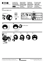
Figure 1: Setting detector address (address 52 shown)
(1) Insert a screwdriver here to set the address
Figure 2: KIR-PHD features
2
(1) Self-locking tab
(2) LED indicator
Testing
Before testing, notify the proper authorities that the fire alarm system is
undergoing maintenance and will be temporarily out of service.
Test each sensor in the detector.
Caution:
Heat damage. Excessive heat may damage the detector
outer cover. Do not apply excessive heat when using a hair dryer.
When using a Testifire detector tester, you must install a Testifire
Adapter Assembly.
Make sure the Testifire Adapter Assembly (model
SIGA2-TSTSPACER) is installed in the Testifire detector tester before
testing. Refer to the
Testifire Adapter Assembly Installation Sheet
(P/N
3101942-ML) for further details.
0
2
3
4
5
6
8
9
0
1
2
3
4
5 6 7 8
9
0
1
11
1
1
2
TENS
ONES
(1)