background image

PLASMA DISPLAY HANGER UNIT

2

H W
A A
N L
G L

R

U
N
I
T

1. 

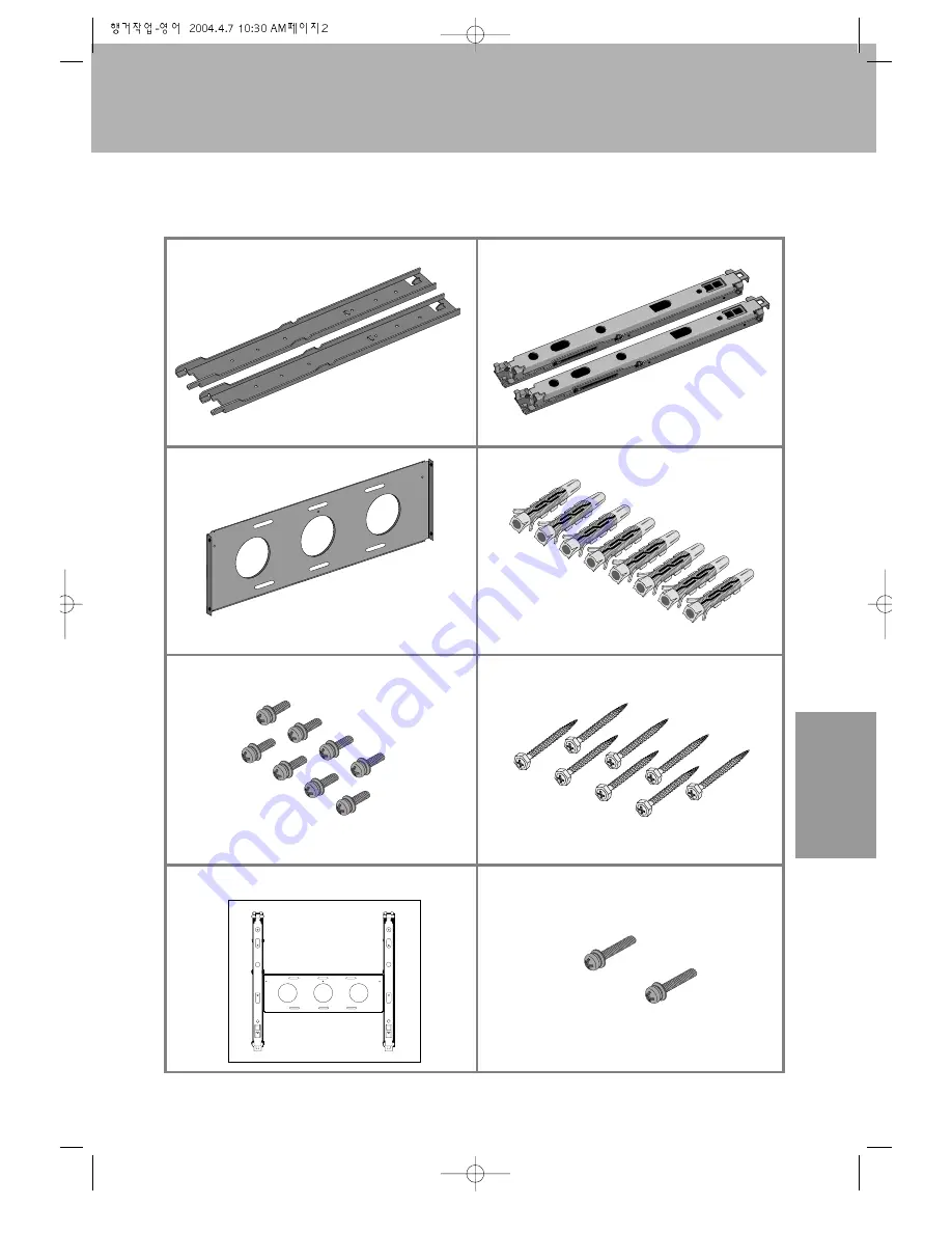
PLEASE CHECK THE ITEMS SHOWN BELOW HAVE BEEN SUPPLIED

(2)

FRAME SET A  

FRAME SET B  

CONNECTING FRAME 

CONCRETE WALL ANCHOR

M5 SCREWS (20 MM)  

WALL SCREWS 

PAPER PATTERN PLAN

M5 SCREWS (30MM) 

(2)

(1)

(8)

(8)

(8)

(1)

(2)

Paper pattern plan

Summary of Contents for DP-HG20

Page 1: ...SPLAY SPEAKER DP SP22 DP SP21 DP SP20 DP HG22 DP HG20 DP ST22 DP ST21 DP ST20 PLASMAMONITOR DISPLAY OPTIONS INSTRUCTION MANUAL PLASMAMONITOR DISPLAY WALLHANGERUNIT PLASMAMONITOR DISPLAY STAND S T A N...

Page 2: ...UCTION MANUAL DP SP22 DP SP21 DP SP20 Thank you for purchasing the Plasma Display Speakers These speakers are specifically designed only for the Plasma Display To ensure the safe operation of the unit...

Page 3: ...1 TABLE OF CONTENTS 1 Check for enclosed parts 2 2 Important Safety Instructions 3 3 Assembly Instructions 5 1 Using speakers when attached to the plasma display 2 Using speakers on stand...

Page 4: ...SPLAY SPEAKER 2 S P E A K E R 1 PLEASECHECKTHE FOLLOWINGITEMS HAVE BEEN SUPPLIED 2 16 2 4 2 4 SPEAKERS M5 SCREWS VIBRATION ABSORBENT SPONGE SPECIAL SCREWS ROUND HEAD SCREWS SPEAKER WIRES FIXED BRACKET...

Page 5: ...ot leave out any part when assembling Please install all parts as directed Do not alter or modify any parts Do not use the speakers with other products These speakers are specifically manufactured to...

Page 6: ...ier or cooking pots where speakers will be exposed to steam or smoke Please be sure to connect inputs and inputs correctly when connecting speakers to plasma display PLEASEFOLLOWTHESESAFETYPRECAUTIONS...

Page 7: ...er that will be attached to the plasma display Please leave a 5 mm space on the top and bottom when attaching Do not cover the entire side with the sponge as shown in the picture above 5mm 2inch 5mm 2...

Page 8: ...ng on and lay the plasma display as shown below Take the speakers with fixed brackets to the back of the plasma display Place the hooks on the fixed brackets to the squared holes in the back of the pl...

Page 9: ...se the red cord to connect to and from inputs and use the black cord to connect to and from inputs 4 Please be sure to connect red wires with and black wires with otherwise speakers will not produce c...

Page 10: ...be sure to have the vibration absorbent sponge on the side of the speaker where the stand will be attached Take the speaker wires 2 and use the red cord to connect to and from inputs and use the black...

Page 11: ...UNIT INSTRUCTION MANUAL DP HG22 DP HG20 Thank you for purchasing the Plasma Display Wall Hanger Unit This wall unit is specifically designed for use with the Plasma Display To ensure the safe operatio...

Page 12: ...NTS 1 Check for enclosed parts 2 2 Important Safety Instructions 3 3 Assembly Instructions 6 4 Adjusting angles after installation 12 To install the wall hanger unit Please consult an Authorized servi...

Page 13: ...N L G L E R U N I T 1 PLEASE CHECK THE ITEMS SHOWN BELOW HAVE BEEN SUPPLIED 2 FRAME SET A FRAME SET B CONNECTING FRAME CONCRETE WALL ANCHOR M5 SCREWS 20 MM WALL SCREWS PAPER PATTERN PLAN M5 SCREWS 30...

Page 14: ...e the unit to vibrate and to fall Failing to do so may cause the unit to fall and break Failing to do so may cause the unit to fall and break To install the wall hanger unit please consult an Authoriz...

Page 15: ...alling please have at least two people Please choose a wall that is straight so that the plasma display can be securely attached onto the wall Place a protective covering over the surface you will be...

Page 16: ...t which can cause fire or damage to the unit When installing please use the size referenced below to choose a place and attach the paper pattern plan to the wall When installing please allow at least...

Page 17: ...Y IS ATTACHED TO THE STAND TO DETACH THE STAND FROM THE PLASMA DISPLAY To avoid unwanted marks on the unit place a protective covering over the surface you will be working on and lay the plasma displa...

Page 18: ...To avoid unwanted marks on the unit place a protective covering over the surface you will be working on and lay the plasma display as shown in the picture below When securing frame set A to the plasm...

Page 19: ...5 to secure them tightly Place the enclosed paper pattern plan actual size on the wall with glue or tape Drill holes on the wall as indicated on the paper pattern plan with a hand drill power drill an...

Page 20: ...pattern plan 3 INSTALLING ON THE WALL HELD BY SUPPORTING WOODEN STRUCTURE If it is not feasible to attach frame set B firmly and completely due to the distance between the two supporting woods attach...

Page 21: ...ttheseframestogether X Y Z Frame set B Frame set A 1 PLASMA DISPLAY HANGER UNIT 10 H W A A N L G L E R U N I T CONNECTING LOWER PART OF FRAME SET A AND FRAME SET B Adhere Frame set B to Plasma Display...

Page 22: ...PROVIDE THE SECUREST FIT After installing plasma display and wall frame sets for a more secure fit secure M5 screws M5x30 on the Z part so that Z will not move up and down as shown in the picture bel...

Page 23: ...t of the frame Insert the upper part of the frame set B angle adjustment lever to its gap 1 2 Lever X 0 10 15 20 As pictured below pull and adjust the lever X to fit your desired viewing angle This ad...

Page 24: ...RUCTION MANUAL DP ST22 DP ST21 DP ST20 Thank you for purchasing the Plasma Monitor stand This stand is specifically designed only for the Plasma Display To ensure the safe operation of the unit please...

Page 25: ...E OF CONTENTS 1 Check for enclosed parts 1 2 Important Safety Instructions 2 3 Assembly Instructions 3 4 Disassemby Instructions 5 1 PLEASE CHECK THE ITEMS SHOWN BELOW HAVE BEEN SUPPLIED 1 STAND M5 SC...

Page 26: ...f working without the protective covering When assembling be sure to use the enclosed parts and make sure all parts are tightly screwed When assembling do not alter or modify any parts When installing...

Page 27: ...ASSEMBLING INSTRUCTIONS HOW TO DISPOSE OF THE PLASMA MONITOR WRAPPER First dispose of the wrapping band and raise the top box to open Afterwards dispose of the Styrofoam and remove the vinyl covering...

Page 28: ...and from the box and remove wrapper Slide the stand under the plasma display like the picture below Use the enclosed 2 M5 screws to secure the assembled stand Picture of a properly installed stand and...

Page 29: ...ng over the surface you will be working on and lay the plasma display as shown below Make sure 2 people handle the unit Completely unscrew the secured 2 screws Pull the stand away from the plasma disp...

Page 30: ......

Reviews: