background image

REMOTE OPERATION 

38


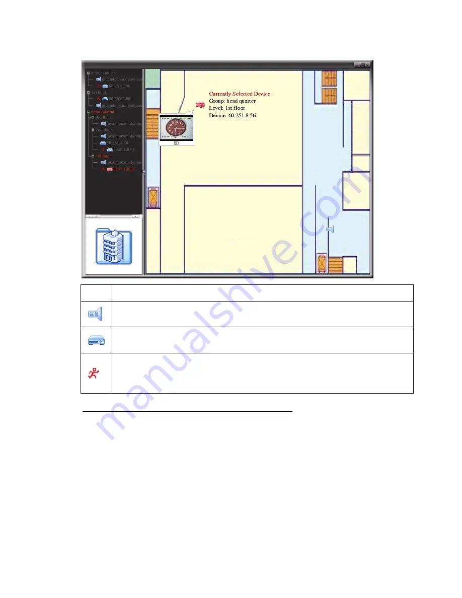
STEP3: When the E-Map group is created, you will see the tree on the top-left panel, 

showing all the devices you’’ve added to this group.   


Icon 

Description 


The connected device is camera. When it’’s selected, it will become red. 


The connected device is DVR. When it’’s selected, it will become red. 


For  any  motion  or  alarm  event,  it  will  appear  on  the  screen  to  catch  your 
attention.   
To  know  what’’s  happening  quickly,  double-click  the  device  icon  on  the 
E-Map to show the live view. 

How to Edit / Remove an Existing E-Map Group 

¾

For Google E-Map Group 

Right-click on the group name to show the shortcut menu list, and select ““Edit 
E-MAP”” or ““Remove E-MAP”” as needed. 
You can also add a single E-Map group (Add Single E-MAP) or Building 
E-Map group (Add Building E-MAP) into the existing Google E-Map group. 

Summary of Contents for 340Z

Page 1: ...57_759_688A_686A_Manual_V1 2 H 264 Network DVR User Manual GUI Display with USB Mouse Control Please read instructions thoroughly before operation and retain it for future reference For the actual display operation please refer to your DVR in hand ...

Page 2: ...ion the product must be collected separately at the product end of life This applies to your product and any peripherals marked with this symbol Do not dispose of these products as unsorted municipal waste Contact your local dealer for procedures for recycling this equipment This apparatus is manufactured to comply with the radio interference requirements Disclaimer The information in this manual ...

Page 3: ...INTERNAL AND COMMERCIAL USES AND LICENSING MAY BE OBTAINED FROM MPEG LA LLC SEE HTTP WWW MPEGLA COM GPL Licensing This product contains codes which are developed by Third Party Companies and which are subject to the GNU General Public License GPL or the GNU Lesser Public License LGPL The GPL Code used in this product is released without warranty and is subject to the copyright of the corresponding...

Page 4: ...ng 11 3 GUI DISPLAY WITH USB MOUSE CONTROL 12 3 1 Connect USB Mouse 12 3 2 Quick Menu Bar 12 3 2 1 Channel Switch 13 3 2 2 PTZ Control Panel 13 3 3 Main Menu 14 4 BASIC OPERATION 15 4 1 Live Page 15 4 2 Record Icon 15 4 3 Playback 16 4 3 1 Playback Control 16 4 3 2 Event Search 17 4 3 3 Audio Playback 17 4 4 User Level Switch 17 4 5 Video Output Switch 17 5 FREQUENTLY USED FUNCTIONS 19 5 1 Quick S...

Page 5: ...d Licensed Software 29 6 1 1 Installation Network Connection 29 6 1 2 Control Panel Overview 31 6 1 3 General Operation 33 6 1 4 E Map 36 6 2 IE Web Browser 41 6 2 1 Event Playback Download 43 APPENDIX 1 SPECIFICATIONS 44 APPENDIX 2 COMPATIBLE USB FLASH DRIVE LIST 48 APPENDIX 3 COMPATIBLE SATA HDD LIST 49 APPENDIX 4 MAIN MENU STRUCTURE 50 APPENDIX 5 DVR BATTERY REPLACEMENT 52 APPENDIX 6 PIN CONFIG...

Page 6: ...ered Timer recording is on Under playback status DVR is powered on 2 Ÿ ź Ż Ź Press Ÿ ź Ż Ź to move up down left right In the playback mode Press to pause playback Press to stop playback Press to fast forward Press to fast rewind 3 MENU Press MENU to enter the main menu 4 ENTER Press ENTER to confirm the setting 5 LIST Event List Search Press to quickly search the recorded files by four event lists...

Page 7: ...y the recorded video clip during the specified time 13 AUDIO SLOW ZOOM Press SLOW ZOOM to select live or playback audio from audio channel 1 4 Live audio from audio channel 1 4 indicated in white Playback audio from audio channel 1 4 indicated in yellow Audio channel unselected 14 P T Z SEQ For Selected Models Only Press SEQ at the same time to enter exit the PTZ control mode 15 USB port There are...

Page 8: ...dio CH1 will be recorded with the video data from video CH1 4 AUDIO OUT Connect to a speaker with 1 mono audio output Note To know how many audio outputs your DVR supports please refer to its specifications 5 MONITOR Connect to a CRT monitor for video output Note When both MONITOR and VGA are connected press the left key Ż on the DVR front panel during DVR power on to force the video output via MO...

Page 9: ... I O port PIN configuration please refer to APPENDIX 6 PIN CONFIGURATION at page 53 10 LAN Connect to Internet by LAN cable 11 DC 19V Connect to the supplied adapter 12 Power Switch Switch to to turn on the power and to turn off the power ...

Page 10: ...when the DVR is powered on and the date time are set correctly to ensure the recorded data are not mixed with other data previously saved in the same hard disk For details please refer to 5 6 4 Clear All HDD Data at page 27 For 16CH 8CH Models Step1 Loose the screws on the upper cover and open the upper cover of the DVR Note The DVR cover is made of metal Please be careful with its edge when you r...

Page 11: ...e HDD to the bracket Note For DVD writer installation please refer to APPENDIX 7 DVD WRITER INSTALLATION at page 56 Step3 Close the upper cover of the DVR and fasten all the screws you loosened in Step1 For 4CH Model Step1 Loose the screws on the upper cover and remove it from the DVR Find the two HDD brackets located on the DVR base Step2 Get a compatible HDD and connect it to the power connector...

Page 12: ...upply Then connect the camera video output to the DVR video input port with a coaxial cable or RCA cable with BNC connectors Note For detailed DVR video input ports please refer to 1 3 Rear Panel at page 3 2 2 1 Normal Camera Connection Note For detailed camera installation and connection please refer to its own user manual 1 Connecting to DVR video input Connect the camera video output to the DVR...

Page 13: ... be different If you cannot control the DVR after connection please reverse the RJ11 cable connection with the DVR STEP 2 Remove one end of the insulating coating of the RJ11 cable Remove one end of the insulating coating of the RJ11 cable to find the RS485 A and the RS485 B wires and remove the insulating coating to reveal the naked wires for further connection STEP 3 Twist the RS485 A and RS485 ...

Page 14: ... CH6 CH7 CH8 CH9 CH10 CH11 W X DETECTION DEVICE PTZ ALERT ID 000 NETWORK PROTOCOL NORMAL SNTP RATE 2400 DISPLAY RECORD REMOTE EXIT 2 3 DVR Power On This device should be operated only with the type of power source indicated on the manufacturer s label Connect the indicated AC power cord to the power adapter and plug into an electrical outlet The power LED will be on Note Before the DVR is powered ...

Page 15: ...ting of DVR power If the DVR time resets after the disconnecting of DVR power for example caused by a power outage the battery might run out and please replace the battery as described in APPENDIX 5 DVR BATTERY REPLACEMENT at page 52 Right click to enter the DVR password with the password keypad The default administrator password is 0000 The status will be changed from key lock to administrator Th...

Page 16: ...PE RS485 VIDEO FORMAT NTSC VERSION 1025 1011 1011 1012 EXIT 2 6 Password Setting Right click to show the main menu and select SYSTEM Æ TOOLS to change the DVR password There are two user levels ADMIN OPERATOR For details please refer to 4 4 User Level Switch at page 17 SYSTEM TOOLS LANGUAGE ENGLISH SYSTEM INFO ADMIN PASSWORD SETUP USB BACKUP OPERATOR PASSWORD SETUP DVD BACKUP UPGRADE SUBMIT EXIT ...

Page 17: ...ain menu SYSTEM Æ TOOLS For details please refer to 4 4 User Level Switch at page 17 Password Input Quick Menu Close 3 2 Quick Menu Bar Move to the arrow mark to extend the quick menu bar and show the five functions as follows Quick Menu Open Click to show the channel switch panel and select the channel you want For details please refer to 3 2 1 Channel Switch at page 13 Click to display the playb...

Page 18: ...1 16 Video Channel Number Click to switch to the channel you want in full screen Sequence Display Click to display each channel in full screen one by one starting from CH1 When the last channel is displayed it will repeat from CH1 again When this function is on will be shown on the status bar Quad Display Press to show the 4 channel display mode 9 Cut Display Press to show the 9 channel display mo...

Page 19: ...fic function that will be enabled when AUTO is clicked For details please refer to the user manual of the PTZ camera Preset point Click to enter the PTZ preset point you want to see 3 3 Main Menu Right click anywhere on the screen to show the main menu as follows and right click again to exit For details about the menu structure please refer to APPENDIX 4 MAIN MENU STRUCTURE at page 50 Main Menu Q...

Page 20: ...onnected Key lock PTZ mode on HDD overwrite Administrator Operator Sequence Motion Recording Alarm 4 2 Record Icon 1 Manual Recording By defaults manual recording is on when the DVR is powered on and a HDD is installed 2 Event Recording When the motion detection or alarm is on the motion icon or alarm icon shows on the screen for any motion or alarm event 3 Timer Recording When timer recording is ...

Page 21: ...se the speed for fast forward Click once to get 4X speed forward and click twice to get 8X speed etc and the maximum speed is 32X Fast Rewind Increase the speed for fast rewind Click once to get 4X speed rewind and click twice to get 8X speed etc and the maximum speed is 32X Play Pause Click to play the latest recorded video clip immediately and click again to pause In the pause mode click once to...

Page 22: ...nel For example the audio data from audio CH1 will be recorded with the video data from video CH1 4 4 User Level Switch In the key lock mode move your USB mouse to display the password input keypad There are two user levels for accessing the DVR Administrator Operator When the administrator password is entered will be shown on the status bar of the screen and all operations are allowed The default...

Page 23: ... on The setting is changed when you hear a short beep sound OR When the DVR is powered on and initialized right click to show the main menu and select ADVANCE CONFIG Æ DISPLAY Æ DISPLAY OUTPUT PATH Select VGA to switch to the connected LCD monitor or COMPOSITE to switch to the connected CRT monitor The DVR will then reboot for the change to take effect ADVANCE CONFIG CAMERA DE INTERLACE For Select...

Page 24: ...rd disk including the video data you want to search or select ALL HDD 3 SEARCH Click START to start search and play the video data immediately 5 2 Record 5 2 1 Quick record setting Right click to display the main menu and select QUICK START Æ GENERAL QUICK START GENERAL CHANNEL TITLE ON TIME SETUP EVENT STATUS ON DATE DISPLAY ON IMAGE SIZE CIF QUALITY SUPER BEST IMAGE PER SECOND 120 EXIT 1 IMAGE S...

Page 25: ...D ENABLE ON ALERT TIMER RECORD ENABLE ON NETWORK EVENT RECORD IPS 120 SNTP TIMER RECORD IPS 120 DISPLAY PRE ALARM RECORD For Selected Models Only ON RECORD OVERWRITE ON REMOTE EVENT RECORD ALL CHANNEL OFF KEEP DATA LIMIT DAYS OFF EXIT 1 MANUAL RECORD ENABLE Set the manual recording function on off 2 EVENT RECORD ENABLE Set the event recording function on off 3 TIMER RECORD ENABLE Set the timer rec...

Page 26: ...ith an event only OFF for any event 9 KEEP DATA LIMIT DAYS Assign the maximum recording days from 01 to 31 after which all the recorded data will be removed or select OFF to disable this function 5 3 Schedule Setting Right click to display the main menu and select SCHEDULE SETTING 5 3 1 Record Timer Click RECORD In RECORD TIMER select ON to enable record timer and select the day and time for this ...

Page 27: ...H6 CH7 CH8 CH9 CH10 CH11 W X DETECTION LS 07 ALERT SS 03 NETWORK TS 02 SNTP DET OFF DISPLAY ALARM OFF RECORD AREA EDIT REMOTE EXIT 1 LS Level of Sensitivity LS is to set the sensitivity of comparing two different images The smaller the value is the higher sensitivity for motion detection The highest sensitivity setting is 00 and the lowest sensitivity setting is 15 The default value is 07 2 SS Spa...

Page 28: ...ivate the motion detection function for the selected channel ON OFF 5 ALARM Select N C N O depending on your installation need The default alarm value is OFF 6 AREA Click EDIT to set the motion detection area There are 16 12 grids per camera for all channels Pink blocks represent the area that is not being detected while the transparent blocks are the area under detection 5 5 PTZ Camera Setting Fo...

Page 29: ... please refer to its user manual 5 6 System Setting 5 6 1 Password Setting Right click to display the main menu and select SYSTEM Æ TOOLS SYSTEM TOOLS LANGUAGE ENGLISH SYSTEM INFO ADMIN PASSWORD SETUP USB BACKUP OPERATOR PASSWORD SETUP DVD BACKUP UPGRADE SUBMIT EXIT 1 ADMIN PASSWORD Click SETUP to change the administrator password The default administrator password is 0000 When you re prompted to ...

Page 30: ...fore using the USB flash drive please use your PC to format the USB flash drive to FAT32 format first For the list of compatible USB flash drives please refer to APPENDIX 2 COMPATIBLE USB FLASH DRIVE LIST at page 48 5 6 3 Video Backup Right click to display the main menu and select SYSTEM Æ USB BACKUP or DVD BACKUP Note DVD BACKUP is only available for selected models Please check the specificatio...

Page 31: ...DD 5 BACKUP Click SUBMIT to start backup 6 REQUIRE SIZE To know the size of the expected backup video before backup click SUBMIT to start calculating Backup File Playback During the backup process a file player installer PLAYER EXE will also be copied into your USB flash drive or disk and you will see the message CHECK PLAYER shown on the screen Note The maximum number of CD R or DVD R backup file...

Page 32: ...DVR date and time are changed accidentally when the recording function is activated Otherwise the recorded data will be disordered and you will not be able to find the recorded file to backup by time search 5 7 Network The description below is only for STATIC network type For PPPOE and DHCP settings you need to set from Video Viewer For details please download the extended user manual for Video Vi...

Page 33: ...CONDARY DNS Key in the IP address of the domain name server obtained from your ISP Internet Service Provider 5 PORT The valid number ranges from 1 to 9999 The default value is 80 Typically the TCP port used by HTTP is 80 However in some cases it is better to change this port number for added flexibility or security 6 SAVE NETWORK SETTING Click APPLY to confirm the settings ...

Page 34: ...wnload the latest version of Video Viewer from the Internet Step3 Follow the on screen instructions to finish the installation When the installation is completed a shortcut icon will be placed on your PC desktop 2 Network Connection L Lo oc ca al l C Co on nn ne ec ct ti io on n v vi ia a L LA AN N LAN is used when it s the first time to remotely access the DVR and you need to configure the networ...

Page 35: ...v vi ia a I In nt te er rn ne et t When the network configuration of your DVR is completed you can access your DVR remotely via Internet a Double click icon on your PC desktop to enter the control panel By defaults the Address Book panel will be displayed on the right side of the control panel b Click Æ to key in the IP address user name password and port number of the DVR you intend to connect OR...

Page 36: ...REMOTE OPERATION 31 6 1 2 Control Panel Overview Two control panels are available and can be switched depending on your use habit Simplified Version Default ...

Page 37: ...in the DVR remotely Remote Config Click to go into the detailed DVR setting Record Setting Click to go to the detailed record setting Miscellaneous Control Custom Setting Click to choose the language of this program The language change will take effect when this program is closed and executed again Log Click to view all event and recording logs search the desired log s by date or playback the reco...

Page 38: ...tting Information Click to show the current network connection details DVR Control Click to go to the DVR control panel to operate the DVR remotely 6 1 3 General Operation Record To record remotely at the same time for any event or alarm at the DVR side click or Ш to go to the Record Setting page In the Record Setting page you can set the following items ΘRecord type ΘHard disk overwriting ΘPre po...

Page 39: ... the specified location Playback To play a recording click or and select the Record tab or Backup tab A list of all the recordings will be shown by defaults and you can also sort out the logs you want to speed up the search time To immediately play a recording select a log from the list and click Play or double click the selected log Network Backup Click Ш or click to go into the Backup page as fo...

Page 40: ... log you want ΘTo view the earlier or later logs that are not shown in the current page click Prev Page or Next Page ΘTo refresh the event list click Reload File Path Assign the location where the backup files are saved Simultaneous Playback To view the backup images simultaneously when the download process is in progress select the checkbox Simultaneous Playback You will see the backup images whi...

Page 41: ...l panel is switch to the full function version How to Add an E Map Group STEP1 In the simplified version click to switch the control panel to the full function version and click to enter the E Map page as follows Note To know where the buttons are please refer to Simplified Version Default at page 31 and Full Function Version at page 32 STEP2 Right click to show the shortcut menu on the top left p...

Page 42: ...REMOTE OPERATION 37 ...

Page 43: ...come red For any motion or alarm event it will appear on the screen to catch your attention To know what s happening quickly double click the device icon on the E Map to show the live view How to Edit Remove an Existing E Map Group For Google E Map Group Right click on the group name to show the shortcut menu list and select Edit E MAP or Remove E MAP as needed You can also add a single E Map grou...

Page 44: ...REMOTE OPERATION 39 For Single E Map Group Right click on the group name to show the shortcut menu list and select Edit E MAP or Remove E MAP as needed ...

Page 45: ... click on the group name to show the shortcut menu list and select Edit Building E MAP or Remove E MAP as needed To edit or remove a certain level of the building E Map group right click on the level name and select Edit E MAP or Remove E MAP as needed ...

Page 46: ...r example for IP address 60 121 46 236 and port No 888 please key in http 60 121 46 236 888 into the URL address box and press Enter Step 2 Enter the user name and password the same as the ones used for video viewer login and click OK You will see a similar screen as the following when the login information is correct NO Function Description 1 Home Click to go to the main page of the DVR 2 Playbac...

Page 47: ...64 QuickTime QuickTime is Apple Inc s multimedia software You need to have QuickTime installed in you operation system first When QuickTime is selected you will be promoted to enter the user name and password to access the server of the DVR 8 Change Quality BEST HIGH NORMAL BASIC Click to change the image quality 9 Change Resolution 4 CIF CIF Click to change the image resolution 4CIF 704 480 CIF 3...

Page 48: ...8X speed etc and the maximum speed is 32X Play Click to play the current video clip Pause Click to pause the video playback Stop Click to stop the video playback Step In the pause mode click to get one frame forward Audio Click to mute the playback if necessary and click again to restore Note Audio is available when your camera supports audio recording and connects to the video channel which suppo...

Page 49: ...IGH NORMAL Hard Disk Storage Accommodates 2 SATA HDDs 1 HDD capacity up to 2TB Quick Search Time Motion Alarm search mode SATA Interface Built in VGA Interface Built in Recording Mode Manual Timer Motion Alarm Remote Multiplex Operation Live display record playback backup network operations USB Mouse Control YES Motion Detection Area 16 12 grids per camera for all channels Motion Detection Sensiti...

Page 50: ...turation Contrast Brightness Date Display Format YY MM DD DD MM YY MM DD YY Daylight Saving YES Power Source 10 DC 19V Power Consumption 10 64 W Operating Temperature 10 40 50 104 к к л л Dimensions mm 432 W 90 H 326 D System Recovery System auto recovery after power failure Optional Peripherals Keyboard controller The specifications are subject to change without notice Dimensional Tolerance 5mm ...

Page 51: ...record playback backup network operations USB Mouse Control YES Motion Detection Area 16 12 grids per camera for all channels Motion Detection Sensitivity 3 adjustable parameters for accurate detection Pre alarm Recording YES NO Backup Device USB 2 0 flash drive Network Web Transmitting Compression Format H 264 Ethernet 10 100 Base T Supports remote control and live view via Ethernet Supports lice...

Page 52: ...t YY MM DD DD MM YY MM DD YY Daylight Saving YES Power Source 10 DC 19V Power Consumption 10 42 W Operating Temperature 10 40 5 к к 0 104 л л Dimensions mm 343 W 59 H 223 D System Recovery System auto recovery after power failure Optional Peripherals Keyboard controller NO The specifications are subject to change without notice Dimensional Tolerance 5mm ...

Page 53: ...use your PC to format the USB flash drive as FAT32 Note You can backup up to 2GB video data for one time USB backup To backup more data please set the time channel s you want and start USB backup again MANUFACTURER MODEL CAPACITY Transcend JFV35 4G JFV30 8G Kingston DataTraveler 1G PQI U172P 4G Apacer AH320 2GB AH320A 8GB AH220 1GB AH320 4GB A data RB 18 1GB Sandisk Cruzer Micro 2G Cruzer Micro 4G...

Page 54: ...320613AS 320GB 7200 rpm ST33500320AS 500GB 7200 rpm ST3750330AS 750GB 7200 rpm Seagate ST31000340AS 1000GB 7200 rpm WD3200AAKS 320GB 7200 rpm WD5000AACS 500GB 7200 rpm WD6400AAKS 640GB 7200 rpm WD7500AAKS 750GB 7200 rpm WD10EADS 1TB 7200 rpm WD15EADS 1 5TB 7200 rpm WD WD20EADS 2TB 7200 rpm STM3500320AS 500GB 7200 rpm Maxtor STM3750330AS 750GB 7200 rpm HDT725032VLA360 320GB 7200 rpm HITACHI HDS7210...

Page 55: ...HDD RESET DEFAULT REMOTE CONTROL ID SERIAL TYPE VIDEO FORMAT VERSION USB BACKUP DVD BACKUP For Selected Models Only EVENT INFORMATION QUICK SEARCH EVENT SEARCH HDD INFO EVENT LOG ADVANCE CONFIG CAMERA BRIGHTNESS CONTRAST SATURATION HUE COV REC CHANNEL TITLE DETECTION LS SS TS DET ALARM AREA ALERT EXT ALERT INT BUZZER KEY BUZZER VLOSS BUZZER MOTION BUZZER ALARM BUZZER HDD BUZZER ALARM DURATION SEC ...

Page 56: ...AY OUTPUT PATH ALPHA BLENDING RECORD MANUAL RECORD ENABLE EVENT RECORD ENABLE TIMER RECORD ENABLE EVENT RECORD IPS TIMER RECORD IPS PRE ALARM RECORD For Selected Models Only OVERWRITE EVENT RECORD ALL CHANNEL KEEP DATA LIMIT DAYS REMOTE For Selected Models Only SCHEDULE SETTING RECORD DETECTION ...

Page 57: ...e The lithium battery CR2032 is a non chargeable battery and should be purchased separately Please replace only with the same or equivalent type battery in case of danger Step1 Stop all DVR recording immediately to prevent the disorder of the recorded data Then back up the recorded data if necessary Step2 Power off the DVR and disconnect the DVR power Step3 Remove the DVR cover and find the batter...

Page 58: ...3 PIN 4 5 CH5 PIN 5 7 CH7 PIN 6 9 CH9 PIN 7 11 CH11 PIN 8 13 CH13 PIN 9 15 CH15 10 11 PIN OFF NA 12 RS485 A 13 EXTERNAL ALARM NO Under the normal operation COM disconnects with NO But when any alarm is triggered COM connects with NO Attention The voltage restriction is under DC24V 1A 14 PIN OFF NA 15 22 ALARM INPUT Connect ALARM INPUT PIN 15 22 and GND PIN 1 connector with wires Once an alarm is t...

Page 59: ...ding video channel PIN 2 1 CH1 PIN 3 3 CH3 PIN 4 5 CH5 PIN 5 7 CH7 6 11 PIN OFF NA 12 RS485 A 13 EXTERNAL ALARM NO Under the normal operation COM disconnects with NO But when any alarm is triggered COM connects with NO Attention The voltage restriction is under DC24V 1A 14 PIN OFF NA 15 18 ALARM INPUT Connect ALARM INPUT PIN 15 18 and GND PIN 1 connector with wires Once an alarm is triggered the D...

Page 60: ...wires Once an alarm is triggered the DVR will start recording and the buzzer will be on PIN Alarm Corresponding video channel PIN 1 1 CH1 PIN 2 2 CH2 PIN 3 3 CH3 PIN 4 4 CH4 5 GND GROUND 6 EXTERNAL ALARM COM Under the normal operation COM disconnects with NO But when any alarm is triggered COM connects with NO Attention The voltage restriction is under DC24V 1A 7 EXTERNAL ALARM NO Under the normal...

Page 61: ...R supports this feature Step1 Remove the DVR cover and find the DVD writer bracket to remove it Step2 Put the DVD writer in the bracket and fix it to the bracket with two screws optional on each side Step3 Connect the data bus and power cables to the SATA DVD writer Data bus power cables are optional Step4 Connect the data bus and power cables to the data bus and power jack on the DVR main board N...

Reviews: