background image

1

Introduction


The U3606B in Brief

18

U3606B User’s Guide

Keypad

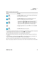
Figure 1-8

The keypad at a glance

11

ms

Pulse width unit for square-wave output

%

Duty cycle unit for square-wave output

V

Voltage unit: V for over-voltage protection

A

Current unit: A for over-current protection

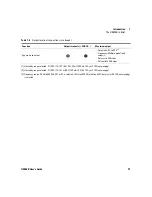
Table 1-3

VFD display descriptions (continued)

Legend

Description

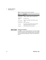
N O T E

Pressing a key changes the current operation, illuminates a related 
annunciator on the display, and generates a key-click sound (a beep).

Summary of Contents for U3606B

Page 1: ...Keysight U3606B Multimeter DC Power Supply User s Guide ...

Page 2: ...THIS PAGE HAS BEEN INTENTIONALLY LEFT BLANK ...

Page 3: ...U3606B User s Guide I ...

Page 4: ...ict with these terms the warranty terms in the separate agreement shall control Technology Licenses The hardware and or software described in this document are furnished under a license and may be used or copied only in accor dance with the terms of such license Restricted Rights Legend U S Government Restricted Rights Soft ware and technical data rights granted to the federal government include o...

Page 5: ...instrument Direct current DC Off supply Alternating current AC On supply Both direct and alternating current Caution risk of danger refer to this manual for specific Warning or Caution information Earth ground terminal Out position of a bi stable push control Frame or chassis terminal In position of a bi stable push control Category II 300 V over voltage protection CAT II 300 V ...

Page 6: ...for cracks or missing plastic Do not operate the device around explosive gas vapor or dust Always use the device with the cables provided Observe all markings on the device before establishing any connection Turn off the device and application system power before connecting to the I O terminals When servicing the device use only the specified replacement parts Do not operate the device with the co...

Page 7: ...0 C Humidity Operating condition Up to 80 RH at 40 C non condensing Storage condition Up to 95 RH at 40 C non condensing Altitude Up to 2000 m Pollution degree 2 NOTE The U3606B complies with the following safety and EMC compliances Safety compliance IEC 61010 1 2001 EN 61010 1 2001 2nd Edition Canada CAN CSA C22 2 No 61010 1 04 USA ANSI UL 61010 1 2004 EMC compliance IEC 61326 1 2005 EN61326 1 20...

Page 8: ... NMB 001 indicates that this ISM device complies with the Canadian ICES 001 Cet appareil ISM est confomre a la norme NMB 001 du Canada This instrument complies with the WEEE Directive 2002 96 EC marking requirement This affixed product label indicates that you must not discard this electrical or electronic product in domestic household waste The CSA mark is a registered trademark of the Canadian S...

Page 9: ...cal or electronic product in domestic household waste Product Category With reference to the equipment types in the WEEE directive Annex 1 this instrument is classified as a Monitoring and Control Instrument product The affixed product label is as shown below Do not dispose in domestic household waste To return this unwanted instrument contact your nearest Keysight Service Center or visit www keys...

Page 10: ...his instrument is available on the Keysight website You can search the DoC by its product model or description at the web address below http regulations products keysight com DoC search htm NOTE If you are unable to search for the respective DoC please contact your local Keysight representative ...

Page 11: ...dle 7 Rack mount the instrument 8 Stack multiple U3606B units 10 The U3606B in Brief 11 Dimensions 11 Overview 12 Display screen 15 Keypad 18 Input Output terminals 24 2 Operation and Features Measuring Voltage 30 Measuring Current 33 Measuring Resistance 36 Testing Continuity 39 Measuring Low Resistance 42 Measuring Capacitance 47 Testing Diodes 50 Measuring Frequency Pulse Width Duty Cycle Volta...

Page 12: ...Multimeter 75 Front panel triggering 76 Remote interface triggering 77 3 DC Power Supply Operation Constant Voltage Operation 80 Constant Current Operation 83 Protection Functions 86 Over voltage protection OVP 86 Over current protection OCP 90 Over voltage limit OV 94 Over current limit OC 97 Square Wave Operation 100 Sweep Functions 106 Ramp signal 106 Scan signal 109 Selecting a Range 113 Enabl...

Page 13: ...put protection state 140 Adjusting the soft start output 141 Selecting a dBm reference resistance value 142 Performing a self test 142 Connecting to a remote interface 143 Configuring the beeper 144 Changing the power on state 145 Adjusting the display brightness 146 Reading the program code revision 146 Storing and Recalling Instrument States 147 Storing a state 148 Recalling a stored state 149 R...

Page 14: ...7 Operating specifications 167 Supplemental characteristics 169 DC Power Supply Specifications 173 Safety considerations 173 Specifications assumptions 173 Performance specifications 174 Supplemental characteristics 176 6 List of Error Messages Error Messages 182 Command errors 183 Execution errors 184 Internal errors 185 Query errors 185 Device specific errors 185 Self test errors 186 Calibration...

Page 15: ...mount dimensions 9 Figure 1 4 U3606B dimensions 11 Figure 1 5 The front panel at a glance 12 Figure 1 6 The rear panel at a glance 13 Figure 1 7 The VFD display at a glance 15 Figure 1 8 The keypad at a glance 18 Figure 1 9 The input output terminals at a glance 24 Figure 3 1 Remote sensing connections 116 Figure 3 2 Local sensing connections 116 ...

Page 16: ...XIV U3606B User s Guide THIS PAGE HAS BEEN INTENTIONALLY LEFT BLANK ...

Page 17: ...ty cycle measurement voltage path summary 55 Table 2 10 Frequency pulse width duty cycle measurement current path summary 58 Table 2 11 Math operations summary 62 Table 3 1 CC mode over voltage protection range and values 88 Table 3 2 CV mode over current protection range and values 92 Table 3 3 CC mode over voltage range and values 96 Table 3 4 CV mode over current range and values 99 Table 3 5 S...

Page 18: ...ance specifications 174 Table 5 9 DC power supply supplemental characteristics 176 Table 5 10 Square wave output characteristics 177 Table 5 11 Scan output characteristics 179 Table 5 12 Ramp output characteristics 179 Table 6 1 List of command errors 183 Table 6 2 List of execution errors 184 Table 6 3 List of internal errors 185 Table 6 4 List of query errors 185 Table 6 5 List of device specifi...

Page 19: ...ment 3 Connect power to the instrument 5 Adjust the carry handle 7 Rack mount the instrument 8 Stack multiple U3606B units 10 The U3606B in Brief 11 Dimensions 11 Overview 12 Display screen 15 Keypad 18 Input Output terminals 24 This chapter teaches you how to set up the U3606B for the first time A summary of all the features of the U3606B is also given ...

Page 20: ...the manual revision on the first page of each manual User s Guide This manual Quick Start Guide Printed copy included with the shipment Programmer s Reference Free download at the Keysight website Safety notes Safety notes are used throughout this manual see the Safety Notices section for format examples Familiarize yourself with each of the notes and its meaning before operating your instrument M...

Page 21: ...hipping container and verify that the standard accessories and your ordered options are included in the shipment according to the standard shipped items list shown below 3 For any question or problems refer to the Keysight contact numbers on the back of this manual Standard shipped items Verify that you have received the following items in the shipment of the U3606B If anything is found missing or...

Page 22: ...e Power cord U8201A combo test lead kit USB Standard A to Type B interface cable Certificate of Calibration Keysight U3606B Product Reference CD ROM Keysight Automation Ready CD ROM Keysight U3606B Multimeter DC Power Supply Keysight U3606B Quick Start Guide ...

Page 23: ... location The U3606B is equipped with a three wire grounding type power cord the third conductor being the ground WARNING The mains plug should only be inserted into a socket outlet that provides protective earth contact CAUTION The U3606B is grounded only when the power line cord is plugged into an appropriate receptacle Do not operate your instrument without adequate ground connection 1 2 3 ...

Page 24: ...error number in the Utility menu A more extensive self test is also available from the Utility menu Push the power switch to turn on the instrument The front panel display illuminates while the U3606B performs its power on self test 4 DC voltage measurement Constant voltage operation Output on standby Autoranging enabled The image above shows the U3606B state after the initial power up DC voltage ...

Page 25: ...Introduction 1 Preparing the U3606B U3606B User s Guide 7 Adjust the carry handle 1 2a 3 2b ...

Page 26: ...Figure 1 1 Single rack mounted U3606B To rack mount two instruments side by side order 1CM011A Be sure to use the support rails inside the rack cabinet This configuration only works for two U3606B mounted side by side Figure 1 2 Two U3606B rack mounted side by side Remove the carrying handle and the front and rear rubber bumpers before rack mounting the instrument 1 To remove the handle rotate it ...

Page 27: ...Introduction 1 Preparing the U3606B U3606B User s Guide 9 Figure 1 3 Rack mount dimensions ...

Page 28: ...de Stack multiple U3606B units You may stack multiple U3606B units on top of each other The rubber bumpers are uniquely designed to secure firmly the units stacked above it preventing any unwanted movements Ensure that the Stackable Direction arrow points up ...

Page 29: ...Introduction 1 The U3606B in Brief U3606B User s Guide 11 The U3606B in Brief Dimensions Figure 1 4 U3606B dimensions 105 mm 334 mm 226 mm ...

Page 30: ... 1 1 Front panel descriptions Legend Description 1 Output terminals Positive and negative terminals for output connections 2 Input terminals Positive terminals and negative terminal shared for input connections 3 Current fuse 3 15 A 500 V F B 6 3 32 mm fuse 4 VFD display Displays the instrument settings and readings 5 Shift Local Selects Shift functions and enables front panel operation during rem...

Page 31: ... glance 6 Power Turns the instrument on or off 7 Keys for multimeter operation Function keys for multimeter operation 8 Autorange and manual range Selects a manual range or enables autoranging for multimeter operation 9 Keys for source operation Function keys for source operation Table 1 1 Front panel descriptions continued Legend Description 3 1 2 9 6 7 10 4 5 8 ...

Page 32: ...at and air from the instrument 4 Kensington security slot Anti theft system using Kensington locks 5 GPIB interface connector GPIB IEEE 488 connector physical interface 6 Chassis ground lug Connect to earth ground or to unit chassis to eliminate noise caused by ground loops 7 Rear output terminals Positive and negative terminals for remote sense 8 Short bars Shorts the rear output and and sense S ...

Page 33: ...0 11 Table 1 3 VFD display descriptions Legend Description 1 A single reading is taken from the input terminals Trig Single trigger operation is active Hold Hold math operation enabled MinMaxAvg MinMax math operation enabled Avg When Avg is flashing the smooth function is enabled Null Null math operation enabled Diode test function selected Continuity test function selected Shift Shift mode select...

Page 34: ... 30 V 1 A or 30 V 100 mA S2 Output range S2 selected 8 V 3 A or 1000 mV 3 A S1S2 Autoranging enabled for constant voltage constant current and square wave output operations V Voltage unit V for constant voltage operation A Current unit A for constant current operation Hz Frequency unit Hz for square wave output DC symbol AC symbol 5 Limit Limit math operation enabled Auto Autoranging selected DC m...

Page 35: ...7 1 8 8 8 8 8 Primary display for multimeter operation 8 ºC Celsius temperature unit ºF Fahrenheit temperature unit dB Decibel unit relative to 1 dBm dBm Decibel unit relative to 1 mW ms Pulse width unit Duty cycle unit MkΩ Resistance units Ω kΩ MΩ MkHz Frequency units Hz kHz MHz mV Voltage units mV V mA Current units mA A μnF Capacitance units nF μF 9 OUT Output is enabled from the output termina...

Page 36: ... output Duty cycle unit for square wave output V Voltage unit V for over voltage protection A Current unit A for over current protection Table 1 3 VFD display descriptions continued Legend Description NOTE Pressing a key changes the current operation illuminates a related annunciator on the display and generates a key click sound a beep ...

Page 37: ...rm a Shift function just press Shift again to turn off the Shift annunciator If no key press is detected 3 seconds after Shift is pressed the instrument will return to normal operation the Shift annunciator turns off 1 2 To select shift functions 1 press Shift first then 2 press the desired key In this example the Lo Ω function is selected Shift annunciator Table 1 4 Keypad descriptions Legend Des...

Page 38: ...n two values to select a value from the list or to decrease or increase a value Press Shift Save to save the changes made in the edit mode Press Shift Exit to exit the edit mode or Utility menu without saving Press Shift Exit to toggle off a math operation Null dBm dB MinMax Limit Hold Press Shift Store to store an instrument state Press Shift Recall to recall a previously stored instrument state ...

Page 39: ...asurement display will flash briefly before the frequency measurement display is shown Press to select the diode test function Press again to select the capacitance function Press Null to enable the null math operation Press Shift dBm to convert the measured voltage value to dBm Press Shift dBm dB to convert the measured voltage value to dB Press MinMax to store statistical data for the present re...

Page 40: ...t to select CC output Use the arrow keys to select a suitable current value Press to select the square wave output Use the arrow keys to set the voltage amplitude Press again to cycle through the duty cycle pulse width and voltage amplitude settings When the annunciator is flashing press or to step through the available frequencies While the annunciator is flashing press or to set the voltage ampl...

Page 41: ... default path when you select the frequency measurement function To switch to the current path for frequency pulse width and duty cycle measurements first press then press Hz ms 2 The refresh hold variation and threshold values can be configured through the Utility menu 3 The continuity and diode test functions have a fixed 4 digit resolution Capacitance measurement is fixed to 3 digit resolution ...

Page 42: ...nect test leads to the front output terminals make sure to disable the U3606B output first to avoid damage to the circuits being connected CAUTION To avoid damaging this device do not exceed the rated input limit Positive input terminals V Positive input terminals I Positive output terminals Negative output terminals Negative input terminals LO Current input fuse ...

Page 43: ...t via the voltage path Capacitance measurement LO 1000 Vrms on all ranges 0 3 A short circuit Diode test LO 1000 Vrms on all ranges 0 3 A short circuit Resistance 2 wire measurement LO 1000 Vrms on all ranges 0 3 A short circuit Continuity test Low resistance 4 wire measurement LO 1000 Vrms on all ranges 0 3 A short circuit 3 15 A 250 V FF fuse DC current measurement I LO 3 15 A 500 V FF fuse AC c...

Page 44: ...S1 0 A to 1 05 A S2 0 A to 3 15 A S2m 0 A to 3 15 A S1S2 0 A to 3 15 A Constant current output Amplitude 0 A to 3 A 2 OVP S1 0 V to 33 V S2 0 V to 8 8 V S1m 0 V to 33 V S1S2 0 V to 33 V OV S1 0 V to 31 5 V S2 0 V to 8 4 V S1m 0 V to 31 5 V S1S2 0 V to 31 5 V Ramp output Amplitude CV 0 V to 31 5 V 1 CC 0 A to 3 15 A 2 Number of steps 1 to 10000 steps Scan output Amplitude CV 0 V to 31 5 V 1 CC 0 A ...

Page 45: ... by range selected S1 30 V 1 A S2 8 V 3 A S2m 1000 mV 3 A or S1S2 autoranging 2 Limited by range selected S1 30 V 1 A S1m 30 V 100 mA S2 8 V 3 A or S1S2 autoranging 3 Frequency range 0 5 Hz to 4800 Hz if S1 or S2 is selected 10 Hz to 4800 Hz with fixed 50 duty cycle if S1S2 autoranging is selected Table 1 6 Output terminal connections continued Function Output terminals FORCE Maximum output ...

Page 46: ...1 Introduction The U3606B in Brief 28 U3606B User s Guide THIS PAGE HAS BEEN INTENTIONALLY LEFT BLANK ...

Page 47: ...asuring Frequency Pulse Width Duty Cycle Voltage Path 53 Measuring Frequency Pulse Width Duty Cycle Current Path 56 Selecting a Range 59 Setting the Resolution 61 Math Operations 62 Null 63 dBm measurements 66 dB measurements 67 MinMax 69 Limit 70 Hold 73 Triggering the Multimeter 75 Front panel triggering 76 Remote interface triggering 77 This chapter describes the various multimeter functions an...

Page 48: ... 30 U3606B User s Guide Measuring Voltage Connect the test leads Select the voltage measurement function 1 2 4 Press again to cycle between DC AC or AC DC measurements V 3 The DC AC or AC DC annunciator will turn on according to your selection ...

Page 49: ...345 V with autoranging enabled and 5 digit resolution selected by default 5 Table 2 1 Voltage measurement summary Item Description DC voltage measurement Available ranges 19 9999 mV 100 000 mV 1 00000 V 10 0000 V 100 000 V 1000 00 V Measurement method Sigma Delta A to D converter Input impedance 10 MΩ 2 range typical in parallel with capacitance 120 pF Input protection 1000 Vrms on all ranges ...

Page 50: ... errors included Limited by the peak input and 100 kHz bandwidth Maximum 3 0 at full scale Peak input 300 of range Limited by maximum input Table 2 1 Voltage measurement summary continued Item Description NOTE Using the AC DC function The U3606B is a true rms multimeter that returns an accurate rms reading not only for sine waves but also other AC signals such as square triangle and staircase wave...

Page 51: ... U3606B User s Guide 33 Measuring Current Connect the test leads Select the current measurement function 1 2 4 Press again to cycle between DC AC or AC DC measurements I 3 The DC AC or AC DC annunciator will turn on according to your selection ...

Page 52: ...and 5 digit resolution selected by default 5 Table 2 2 Current measurement summary Item Description DC current measurement Available ranges 10 0000 mA 100 000 mA 1 00000 A 3 0000 A Measurement method Sigma Delta A to D converter Burden voltage and shunt resistance 0 2 V 10 Ω for 10 mA range 0 2 V 1 Ω for 100 mA range 0 3 V 0 05 Ω for 1 A range 0 7 V 0 05 Ω for 3 A range Input protection Protected ...

Page 53: ...imum 3 0 at full scale Peak input 300 of range Limited by maximum input Table 2 2 Current measurement summary continued Item Description NOTE Please expect some delay when obtaining a stable AC current reading on the following test conditions The signal has a large DC current offset comparable to the AC current signal Changes on the range function NOTE Using the AC DC function The U3606B is a true...

Page 54: ...ce 36 U3606B User s Guide Measuring Resistance Connect the test leads Select the resistance measurement function 1 2 4 Press to switch between resistance measurements and continuity tests 3 The Ω annunciator turns on for resistance measurements ...

Page 55: ...e obtain a resistance measurement of 1 2345 kΩ with autoranging enabled and 5 digit resolution selected by default Test current 5 CAUTION Disconnect circuit power and discharge all high voltage capacitors before measuring resistance or conductance or testing circuit continuity to avoid damaging the U3606B or the device under test ...

Page 56: ...ment summary Table 2 3 Resistance measurement summary Item Description Available ranges 100 000 Ω 1 00000 kΩ 10 0000 kΩ 100 000 kΩ 1 00000 MΩ 10 0000 MΩ 100 000 MΩ Measurement method Two wire open circuit voltage limited to 5 V Input protection 1000 Vrms on all ranges 0 3 A short circuit ...

Page 57: ... 2 Testing Continuity U3606B User s Guide 39 Testing Continuity Connect the test leads Select the continuity test function 1 2 4 Press to switch between resistance measurements and continuity tests 3 The annunciator turns on ...

Page 58: ...sts Test current 5 CAUTION Disconnect circuit power and discharge all high voltage capacitors before measuring resistance or conductance or testing circuit continuity to avoid damaging the U3606B or the device under test NOTE Beeps when a short is detected The U3606B beeps when the continuity measurement is less than or equal to the continuity threshold This allows you to quickly determine shorts ...

Page 59: ... 2 4 Continuity test summary Item Description Measurement method 0 83 mA 0 2 constant current source open circuit voltage limited to 5 V Audible tone Continuous beep when reading is less than threshold resistance of 10 Ω at 1 0 kΩ range Input protection 1000 Vrms on all ranges 0 3 A short circuit ...

Page 60: ...2 Operation and Features Measuring Low Resistance 42 U3606B User s Guide Measuring Low Resistance Connect the test leads 1 2 3 4 ...

Page 61: ...robe the test points and read the display 6 5 The Lo Ω annunciator turns on for low resistance measurements In this example we obtain a resistance measurement of 12 345 mΩ with autoranging enabled and 5 digit resolution selected by default Test current CAUTION The load wattage must be able to handle the applied current 7 ...

Page 62: ...re low resistance measurements To unlock the DC power supply functions exit the low resistance Lo Ω measurement by selecting another multimeter measurement NOTE Delayed response for low resistance readings For measuring low resistance a delayed response should be expected from the front panel display For remote interface operation increase the SCPI query time out value typically 15000 ms Table 2 5...

Page 63: ...etection current Test current 2 2 Press Current to change the test current selected see page 46 Default Range Min Max 100 mΩ 0 015 A 1 0000 A S2 A 1 0000 A 3 0000 A 1000 mΩ 0 015 A 0 1000 A S1 A 0 1000 A 0 3000 A 10 Ω X mA 3 3 X follows the test current setting of 1000 Ω range 50 0 mA S1 mA 50 0 mA 100 0 mA 100 Ω X mA 3 10 0 mA S1 mA 4 0 mA 30 0 mA 1000 Ω X mA 3 6 0 mA S1 mA 4 0 mA 10 0 mA ...

Page 64: ... the low resistance test current Use the arrow keys to navigate the edit mode Enable the low resistance function first 1 2 Press or to select a digit position or range Press or to increase or decrease the value selected To save the changes 3a To exit the edit mode without saving 3b ...

Page 65: ...nce U3606B User s Guide 47 Measuring Capacitance Connect the test leads Select the capacitance measurement function 1 2 4 Press to switch between capacitance measurements and diode tests 3 The F annunciator turns on for capacitance measurements ...

Page 66: ...rement of 1 123 nF Autoranging is enabled by default and the resolution is fixed at 3 digit for capacitance measurements 5 CAUTION Disconnect circuit power and discharge all high voltage capacitors before measuring capacitance to avoid damaging the U3606B or the device under test To confirm that a capacitor has fully discharged use the DC voltage measurement ...

Page 67: ...ance value is obtained For measuring capacitance values greater than 1 mF a delayed response should be expected from the front panel display For remote interface operation increase the SCPI query time out value Typically 10000 ms For measuring small capacitance values press Null with the test leads open to subtract the residual capacitance of the instrument and leads Table 2 7 Capacitance measurem...

Page 68: ...and Features Testing Diodes 50 U3606B User s Guide Testing Diodes Connect the test leads Select the diode test function 1 2 4 Press to switch between capacitance measurements and diode tests 3 The annunciator turns ...

Page 69: ...ample we obtain an open result from a reverse bias diode This response indicates that the diode is good Test current 5 In this example we obtain a voltage measurement of 0 4321 V from a forward bias diode This response indicates that the diode is good The resolution is fixed at 4 digit for diode tests Test current 6 ...

Page 70: ...oximately 1 2 V The forward bias of a typical diode is within the range of 0 3 V to 0 8 V A diode is considered good if the multimeter displays OPEn in reverse bias mode A diode is considered shorted if the multimeter displays approximately 0 V in both forward and reverse bias modes and the U3606B beeps continuously A diode is considered open if the multimeter displays OPEn in both forward and rev...

Page 71: ...er s Guide 53 Measuring Frequency Pulse Width Duty Cycle Voltage Path Connect the test leads Select the frequency measurement function 1 2 4 Press Hz ms again to cycle between frequency pulse width or duty cycle measurements 3 The Hz ms or annunciator will turn on according to your selection ...

Page 72: ...default 5 CAUTION If the frequency signal measured is below 20 Hz you must manually set the range of the AC voltage or AC current measurement to acquire a stable reading NOTE The range and resolution of the frequency pulse width and duty cycle measurement follows the configuration of the AC voltage or AC current measurement dependent on the path chosen The AC voltage or AC current measurement disp...

Page 73: ...Table 2 9 Frequency pulse width duty cycle measurement voltage path summary Item Description Available ranges 100 000 mV 1 00000 V 10 0000 V 100 000 V 750 00 V range is based on the voltage level of the signal not frequency Measurement method Reciprocal counting technique Signal level 10 of range to full scale input on all ranges Input protection 750 Vrms on all ranges ...

Page 74: ... User s Guide Measuring Frequency Pulse Width Duty Cycle Current Path Connect the test leads Select the frequency measurement function 1 2 4 Press Hz ms again to cycle between frequency pulse width or duty cycle measurements 3 The Hz ms or annunciator will turn on according to your selection ...

Page 75: ...efault 5 CAUTION If the frequency signal measured is below 20 Hz you must manually set the range of the AC voltage or AC current measurement to acquire a stable reading NOTE The range and resolution of the frequency pulse width and duty cycle measurement follows the configuration of the AC voltage or AC current measurement dependent on the path chosen The AC voltage or AC current measurement displ...

Page 76: ...le 2 10 Frequency pulse width duty cycle measurement current path summary Item Description Available ranges 10 0000 mA 100 000 mA 1 00000 A 3 0000 A range is based on the current level of the signal not frequency Measurement method Reciprocal counting technique Signal level 10 of range to full scale input on all ranges Input protection Protected with a 3 15 A 500 V FF fuse ...

Page 77: ...is convenient because the U3606B automatically selects the appropriate range for sensing and displaying each measurement However manual ranging results in better performance since the U3606B does not have to determine which range to use for each measurement Key Description Press to select a higher range and disable autoranging Press to select a lower range and disable autoranging Press Shift Auto ...

Page 78: ...from the front panel or 9 9E 37 from the remote interface For frequency pulse width and duty cycle measurements ranging applies to the input voltage or input current of the signal not its frequency The range is fixed for diode 1 Vdc range tests The U3606B remembers the selected ranging method auto or manual and the selected manual range for each measurement function Autorange thresholds The U3606B...

Page 79: ...and duty cycle measurements NOTE 5 digit readings have the best accuracy and noise rejection 4 digit readings provide for faster readings The range and resolution of the frequency pulse width and duty cycle measurements follows the configuration of the AC voltage or the AC current function Continuity and diode tests have a fixed 4 digit display Capacitance measurements have a fixed 3 digit display...

Page 80: ...readings limit testing and a hold function The table below describes the math operations that can be used with each measurement function Table 2 11 Math operations summary Measurement function Allowed math operation Null dBm dB Min Max Limit Hold DC voltage DC current AC voltage AC current AC DC voltage AC DC current Resistance Low resistance Frequency Pulse width Duty cycle Capacitance Continuity...

Page 81: ...All math operations can be toggled off by pressing Shift Exit All math operations are automatically turned off when changing measuring functions Range changing is allowed for all math operations except for the Hold function For remote operation refer to the CALCulate subsystem in the U3606B Programmer s Reference Result reading null value NOTE Null can be set for both auto and manual range setting...

Page 82: ...2 Operation and Features Math Operations 64 U3606B User s Guide Enable the null function To disable the null function ...

Page 83: ...6B User s Guide 65 Edit the null value Use the arrow keys to navigate the edit mode 1 2 Press or to select a digit position or range Press or to increase or decrease the value selected To save the changes 3a To exit the edit mode without saving 3b ...

Page 84: ...00 Ω Voltage measurement is then converted to dBm The dBm function is logarithmic and is based on a calculation of power delivered to a reference resistance relative to 1 mW The formula used for calculating dBm measurements is You can select the reference resistance value through the Utility menu The default setting is 600 Ω NOTE This math operation applies to voltage measurements only dBm 10 log1...

Page 85: ...d immediately produces the dB calculation The formula used for calculating dB measurements is The relative value can take any value between 0 dBm and 120 000 dBm The default relative value is 0 dBm You can either let the instrument automatically measure this value or you can enter a specific value dB reading in dBm relative value in dBm NOTE This math operation applies to voltage measurements only...

Page 86: ...06B User s Guide Edit the relative value Use the arrow keys to navigate the edit mode 1 2 Press or to select a digit position or range Press or to increase or decrease the value selected To save the changes 3a To exit the edit mode without saving 3b ...

Page 87: ...reading MaxMinAvg NOTE This math operation applies to all measurement functions except continuity and diode test The stored statistical data are cleared when statistics are enabled when the CALculate FUNCtion command is sent while the CALCulate STATe is ON when the power is turned off after a Factory Reset RST command after an Instrument Preset SYSTem PRESet command or after a measurement function...

Page 88: ...is stored the instrument beeps once if the beeper is enabled The U3606B calculates the average of all readings and records the number of readings taken since the MinMax function was enabled Accumulated statistics are Max maximum reading since the MinMax function was enabled Min minimum reading since the MinMax function was enabled Avg average of all readings since the MinMax function was enabled M...

Page 89: ... within the specified limits HI Reading is above the high limit LO Reading is below the low limit To disable the Limit function NOTE Each time the input value transitions from PASS to HI or from PASS to LO or when transitioning directly from HI to LO or LO to HI the U3606B beeps once if the beeper is enabled ...

Page 90: ...pper and lower limit values Use the arrow keys to navigate the edit mode Save the changes to edit the next limit 1 2 Press or to select a digit position or range Press or to increase or decrease the value selected To save the changes 3a To exit the edit mode without saving 3b ...

Page 91: ...the primary display when the variation of the measured value exceeds the variation preset in the Utility menu The instrument beeps once if the beeper is enabled when a reading value is updated Set the variation to OFF in the Utility menu to enable data hold In data hold mode the reading is not updated even if the input signal value changes The reading held will remain on the display until you exit...

Page 92: ...2 Operation and Features Math Operations 74 U3606B User s Guide Enable the Hold function To disable the Hold function ...

Page 93: ...ssible for the selected measurement configuration You can enable the single trigger function to manually trigger the U3606B readings see page 76 From the remote interface triggering the U3606B is a three step process 1 Configure the U3606B for measurement by selecting the function range resolution and so on 2 Specify the U3606B trigger source The U3606B will accept a software bus command or an imm...

Page 94: ...gle triggering The U3606B takes one reading each time you press Trig NOTE The single trigger mode is available from the local interface only Enable the single trigger function 1 To disable the Trig function 3 Press Trig again to capture another reading Note that you do not need to press Shift again 2 ...

Page 95: ... must place the instrument in the wait for trigger state using the INITiate IMMediate or READ command A trigger will not be accepted from the selected trigger source until the instrument is in the wait for trigger state Refer to the U3606B Programmer s Reference for the syntax and complete descriptions for these commands Software bus triggering The bus trigger mode corresponds in function as the S...

Page 96: ...6B and returns a measurement The READ command does not overwrite the bus trigger and if selected generates an error It will only trigger the instrument and return a measurement when the IMMEdiate trigger is selected The INITiate command only initiates the measurement and needs a trigger TRG command to make the actual measurement Refer to the U3606B Programmer s Reference for the syntax and complet...

Page 97: ...ions 86 Over voltage protection OVP 86 Over current protection OCP 90 Over voltage limit OV 94 Over current limit OC 97 Square Wave Operation 100 Sweep Functions 106 Ramp signal 106 Scan signal 109 Selecting a Range 113 Enabling the Output 114 Remote Sensing 115 This chapter contains examples on how to operate the DC power supply from the front panel ...

Page 98: ...3 DC Power Supply Operation Constant Voltage Operation 80 U3606B User s Guide Constant Voltage Operation Connect the load 1 LOAD 3 2 ...

Page 99: ...CV annunciator will turn on according to your selection Use the arrow keys to change the value Press or to select a digit position or range Press or to increase or decrease the value selected Note If the CV annunciator is not flashing press Voltage again The output voltage can be programmed when the output is enabled OUT or disabled SBY 6 To exit the edit mode 7 ...

Page 100: ... The output voltage is limited by the range selected Press Shift Range to select an appropriate range You can only select a range when the output is disabled the SBY annunciator is illuminated While adjusting the constant voltage value you can also press Voltage again or Shift Exit to exit the edit mode ...

Page 101: ...DC Power Supply Operation 3 Constant Current Operation U3606B User s Guide 83 Constant Current Operation Connect the load 1 LOAD 3 2 ...

Page 102: ...CC annunciator will turn on according to your selection Use the arrow keys to change the value Press or to select a digit position or range Press or to increase or decrease the value selected Note If the CC annunciator is not flashing press Current again The output current can be programmed when the output is enabled OUT or disabled SBY 6 To exit the edit mode 7 ...

Page 103: ... The output current is limited by the range selected Press Shift Range to select an appropriate range You can only select a range when the output is disabled the SBY annunciator is illuminated While adjusting the constant current value you can also press Current again or Shift Exit to exit the edit mode ...

Page 104: ... to draw more voltage than required such that it exceeds the programmed protection value the over voltage protection circuit will protect the load by disabling the output The following steps shows you how to set the OVP trip level how to check OVP operation and how to clear the OVP condition NOTE Setting the OVP trip level will not activate the OVP feature To activate the OVP feature you will need...

Page 105: ...will turn on according to your selection Use the arrow keys to change the value Press or to select a digit position or range Press or to increase or decrease the value selected Note The OVP value is set to the maximum protection limits by default 5 To save the changes You can recall the OVP value set when you select LASt in the P on Utility menu item page 145 6 ...

Page 106: ...rrent mode You can disable the OVP feature by disabling the output protection state from the Utility menu If the OVP value is set to a lesser value than the OV value the OV value will be adjusted to equal the OVP value The OVP value is not applicable for square wave output The OVP value is limited by the range selected Press Shift Range to select an appropriate range You can only select a range wh...

Page 107: ... turn the output off again When the OVP circuit trips the U3606B will immediately prompt you to change the OVP trip level Use the arrow keys to select a higher OVP trip level and press Shift Save or Protect to save the changes Alternatively press Shift Exit to exit the edit mode without changing the OVP trip level You may read and clear the error message by accessing the Utility menu If the OVP co...

Page 108: ... exceeds the programmed protection value This protection is useful when the load is sensitive to an over current condition The following steps shows you how to set the OCP trip level how to check OCP operation and how to clear the OCP condition NOTE Setting the OCP trip level will not activate the OCP feature To activate the OCP feature you will need to enable the output protection state from the ...

Page 109: ...will turn on according to your selection Use the arrow keys to change the value Press or to select a digit position or range Press or to increase or decrease the value selected Note The OCP value is set to the maximum protection limits by default 5 6 To save the changes You can recall the OCP value set when you select LASt in the P on Utility menu item page 145 ...

Page 110: ...rent mode You can disable the OCP feature by disabling the output protection state from the Utility menu If the OCP value is set to a lesser value than the OC value the OC value will be adjusted to equal the OCP value The OCP value is not applicable for square wave output The OCP value is limited by the range selected Press Shift Range to select an appropriate range You can only select a range whe...

Page 111: ... you to change the OCP trip level Use the arrow keys to select a higher OCP trip level and press Shift Save or Protect to save the changes Alternatively press Shift Exit to exit the edit mode without changing the OCP trip level You may read and clear the error message by accessing the Utility menu If the OCP continues to trip try lowering the regulated output current or raising the OCP trip level ...

Page 112: ...nd the programmed over voltage limit If the load effect exceeds the programmed over voltage limit the CC output will be lowered to maintain the output power across the load The combination of the OV and OVP features create a closed loop circuit protection for sensitive load behaviors Select the constant current function 1 The CC annunciator will turn on according to your selection 2 ...

Page 113: ...will turn on according to your selection Use the arrow keys to change the value Press or to select a digit position or range Press or to increase or decrease the value selected Note The OV value is set to the maximum protection limits by default 5 To save the changes You can recall the OV value set when you select LASt in the P on Utility menu item page 145 6 ...

Page 114: ...l the OV value If the OV value is set to zero this will result in the output current being dropped to zero for limiting The OV value is not applicable for square wave output The OV value is limited by the range selected Press Shift Range to select an appropriate range You can only select a range when the output is disabled the SBY annunciator is illuminated Table 3 3 CC mode over voltage range and...

Page 115: ...nd the programmed over current limit If the load effect exceeds the programmed over current limit the CV output will be lowered to maintain the output power across the load The combination of the OC and OCP features create a closed loop circuit protection for sensitive load behaviors Select the constant current function 1 The CV annunciator will turn on according to your selection 2 ...

Page 116: ...will turn on according to your selection Use the arrow keys to change the value Press or to select a digit position or range Press or to increase or decrease the value selected Note The OC value is set to the maximum protection limits by default 5 To save the changes You can recall the OC value set when you select LASt in the P on Utility menu item page 145 6 ...

Page 117: ...l the OC value If the OC value is set to zero this will result in the output voltage being dropped to zero for limiting The OC value is not applicable for square wave output The OC value is limited by the range selected Press Shift Range to select an appropriate range You can only select a range when the output is disabled the SBY annunciator is illuminated Table 3 4 CV mode over current range and...

Page 118: ...or many applications such as pulse width modulation PWM output adjustable voltage control and synchronous clock baud rate generator You can also use this function to check and calibrate flow meter displays counters tachometers oscilloscopes frequency converter frequency transmitter and other frequency input devices Connect the load 1 LOAD 3 2 ...

Page 119: ...n U3606B User s Guide 101 Select the square wave function View the amplitude duty cycle and pulse width values 5 LOAD 4 The annunciator will turn on according to your selection Press again to cycle between amplitude duty cycle or pulse width values 6 ...

Page 120: ...3 DC Power Supply Operation Square Wave Operation 102 U3606B User s Guide Enable the output 7 ...

Page 121: ...just the amplitude value and save the changes Press again to cycle between amplitude duty cycle or pulse width values 1 Use the arrow keys to change the value Press or to select a digit position or range Press or to increase or decrease the value selected Note If the annunciator is not flashing press again 2 To exit the edit mode 3 ...

Page 122: ...on the display 4 To exit the edit mode 5 NOTE Pressing again will save the changes and display the next square wave parameter While still in the edit mode While adjusting the amplitude duty cycle and pulse width values you can also press Shift Exit to exit the edit mode The square wave amplitude is limited by the range selected Press Shift Range to select an appropriate range You can only select a...

Page 123: ... 5 Hz 2 Hz 5 Hz 4800 Hz or 10 Hz to 4800 Hz if range S1S2 autoranging is selected If range S1S2 autoranging is selected the duty cycle is fixed at 50 The duty cycle can be stepped through 256 steps where each step is 0 390625 more than the previous step The best resolution the display can offer is 0 001 The pulse width can be stepped through 256 steps where each step is 1 256 frequency more than t...

Page 124: ... signal length is based on the following parameters the amplitude end position and the number of steps required to reach the amplitude end position You can configure the ramp signal amplitude end position and number of steps in the Utility menu The ramp dwelling time will be set to the fastest of the instrument capability typically 100 ms per step A higher number of steps provides a more linear ra...

Page 125: ...DC Power Supply Operation 3 Sweep Functions U3606B User s Guide 107 Connect the load 1 LOAD 3 2 ...

Page 126: ...tant voltage or constant current function Select the ramp function and enable the output 5 OR 4 The CV or CC annunciator will turn on according to your selection Press Sweep to switch the between ramp and scan functions The Ramp annunciator will turn on according to your selection 6 7 ...

Page 127: ...ength in the Utility menu NOTE The typical ramp dwelling time per step in the U3606B is measured at 100 ms A longer delay time should be expected if a high number of steps is programmed As an example a 1000 step ramp signal will yield a 200 seconds 1000 100 ms 2 total dwelling time If you want to adjust the ramp signal parameters press Shift Utility to access the Utility menu The maximum amplitude...

Page 128: ...total dwell time will increase with respect to the number of steps and the scan dwell time per step selected The scan dwell time is defined as the length of time the scan signal will dwell in the present step before incrementing to the next step Connect the load 1 LOAD 3 2 ...

Page 129: ...tant voltage or constant current function Select the scan function and enable the output 5 OR 4 The CV or CC annunciator will turn on according to your selection Press Sweep to switch the between ramp and scan functions The Scan annunciator will turn on according to your selection 6 7 ...

Page 130: ... step at amplitude 0 An initial delay the length of the preset scan dwell time is expected for each complete scan signal sweep If you want to adjust the scan signal parameters press Shift Utility to access the Utility menu The maximum amplitude end position will be limited by the range and function CV or CC selected ...

Page 131: ...ilable ranges affect sweep functions ramp and scan OCP and OC values CC 2 2 Available ranges affect sweep functions ramp and scan OVP and OV values Square wave S1 30 V 1 A S2 8 V 3 A S1m 30 V 100 mA S2m 1000 mV 3 A S1S2 autoranging NOTE The S1 range is selected by default You cannot change the range when the output is enabled OUT The output should always be on stand by SBY before the range or outp...

Page 132: ...ff power to the instrument When the output is disabled the output voltage and current go to zero and the SBY annunciator is illuminated When the output is enabled the U3606B regulates the output voltage and current at the selected value and the OUT annunciator is illuminated The output state is stored in volatile memory the output is always disabled when power has been turned off or after a remote...

Page 133: ...tage at the remote sense points By connecting the power supply for remote voltage sensing voltage is sensed at the load rather than at the U3606B output terminals FORCE This will allow the U3606B to automatically compensate for the voltage drop in applications with long lead lengths as well as to accurately read back the voltage across the load Refer to Chapter 5 Characteristics and Specifications...

Page 134: ...necting the sensing leads to the load Figure 3 1 Remote sensing connections Figure 3 2 Local sensing connections NOTE The metal shorting bars should be removed from the rear output and sense terminals for remote sensing connections For local voltage sensing connections the sense leads must be connected to the output terminals S S LOAD Rear output terminals Shielded two wire cable S S LOAD Rear out...

Page 135: ...al block 1 Turn off the power Remove all connections between the front output terminals and the load Remove any metal shorting bars connected to the rear output terminals 2 Loosen the two captive screws in the rear output terminal block with a slotted screwdriver 3 Gently pull the rear output terminal block out ...

Page 136: ...end only The other end of the shield should be left unconnected Observe the polarity when connecting the sensing leads to the load You can connect the output leads to either one of the two or terminals They are internally shorted 5 Tighten the top screws of the rear output terminal block to secure firmly the sensing and output connections 6 Place the rear output terminal block back in place and ti...

Page 137: ...119 Do not loosen the top screws of the rear output terminal block at a tilted angled CAUTION Avoid connecting the load leads from the rear terminal block to the load as shown above Loosening the top screws at an inclined angle will damage the terminal block screws ...

Page 138: ... leads to the load 3 Turn on the U3606B 4 Press Voltage to select the constant voltage mode Use the arrow keys to select the appropriate constant voltage value 5 Press Shift EXT to enable remote sensing When the U3606B is operating in remote sensing mode the EXT annunciator on the front panel is illuminated 6 Press to regulate the output voltage 7 Press Shift EXT again to disable remote sensing wh...

Page 139: ...ation The voltage load regulation specification in Chapter 5 Characteristics and Specifications starting on page 155 applies at the output terminals of the U3606B When remote sensing add 5 mV to this specification for each 1 V drop between the positive sensing point S and output terminals due to the change in load current Because the sense leads are part of the U3606B feedback path keep the resist...

Page 140: ...the maximum output voltage is exceeded Output noise Any noise picked up on the sense leads also appears at the output of the U3606B and may adversely affect the voltage load regulation Twist the sense leads to minimize external noise pickup and run them parallel and close to the load leads In noisy environments it may be necessary to shield the sense leads Ground the shield at the U3606B end only ...

Page 141: ...otection state 140 Adjusting the soft start output 141 Selecting a dBm reference resistance value 142 Performing a self test 142 Connecting to a remote interface 143 Configuring the beeper 144 Changing the power on state 145 Adjusting the display brightness 146 Reading the program code revision 146 Storing and Recalling Instrument States 147 Storing a state 148 Recalling a stored state 149 Remote ...

Page 142: ...uch as on or off Select a value from the list Decrease or increase a value by using the directional keys The Utility menu also displays error messages and hardware revision codes The contents of the Utility menu are summarized in Table 4 1 Key Description Press Shift Utility to access the Utility menu Press or to step through the menu items Press or to switch between two values to select a value f...

Page 143: ...avigate the Utility menu Press Shift Save to save a changed setting Press Shift Exit to exit the Utility menu 1 Present setting Menu item 2 Press or to step through the available menu items Press or to switch between two values to select a value from the list or to decrease or increase a value 3 4 The U3606B resumes normal operation The saved settings are store in the U3606B s non volatile memory ...

Page 144: ...00 Set the data logging interval time NNNNN s from 1 s to 99999 s page 130 LoG FiLE StoP Cont StArt Select StArt to start the data logging operation this operation overwrites any previously logged data Select StoP to stop the data logging operation Select Cont to resume a data logging operation from where it was last stopped page 131 rHoLd t NNN nH N N Set the refresh hold variation t NNN in perce...

Page 145: ... divided by the number of steps NNN Set the scan dwelling time NN s from 1 s to 99 s rAMP CV CC Press Voltage to select ramp setup for CV Press Current to select ramp setup for CC page 138 S1 S2 S2m S1 S1m S2 Press Shift Range to toggle between range S1 30 V 1 A S1m 30 V 100 mA S2 8 V 3 A or S2m 1000 mV 3 A NN NNN V N NNNN A NNNNN The increment of each step will be the amplitude end position NNNN ...

Page 146: ...mmunication port page 143 NN Set the GPIB address from 1 to 30 bEEP 2400 Hz 3840 Hz oFF Set the beep driving frequency to 2400 Hz or 3840 Hz Set oFF to disable the beep tone page 144 P on rESEt LASt Set LASt to recall the last known power off state when power is turned on Set rESEt to recall the default factory power on state when power is turned on page 145 diSP L 03 L 02 L 01 Cycle through the V...

Page 147: ...lay and NN is shown in the lower secondary display where NN is the total number of errors in the error queue For example if there are seven errors in the queue 07 will be shown in the lower secondary display Errors are numbered and stored in the queue in the order they occurred If there are errors in the error queue press to read the first error The error number in the queue is shown in the primar...

Page 148: ...is Since data is stored in the non volatile memory the data remains saved even when the U3606B is turned OFF The data logging feature collects measurement information over a user specified duration Press or to change the data logging loop number 1 to 29000 Press or until the cursor is position on the data logging interval Press or to change the data logging interval 1 to 99999 s NOTE You can recor...

Page 149: ... Utility menu immediately and begin the data logging operation The LOG annunciator turns on for the entire duration of the data logging operation NOTE Selecting StArt overwrites any previously stored data After the data logging operation has started you will need to press Local if you want to stop the data logging operation The data logging operation will stop automatically when it is completed or...

Page 150: ...the refresh hold threshold nH N N Press or to change the refresh hold threshold 0 0 to 9 9 for voltage current and capacitance measurements NOTE If the variation of the measured value exceeds the preset percentage the refresh hold will be ready to trigger For voltage current and capacitance measurements the reading value will not be updated when the reading falls below the threshold value ...

Page 151: ...om the Utility menu The smooth function also includes a fluctuation count which limits the range of the readings that can be used for the averaging Smoothed readings obtained using the smooth function are easier to read as the readings are stabilized The smooth function and the average function of the MinMax operation are independent functions and mutually exclusive in which they cannot occur at t...

Page 152: ...with a 5 V signal and a fluctuation count of 1 0 will only smooth the input raw signal to the existing smooth calculation if the input signal is between 4 9 V and 5 1 V The next input signal will then be compared to the newly smoothed signal If the input signal is out of the set fluctuation count range of the smoothed signal the smooth function calculation will reset and restart at the out of rang...

Page 153: ... set to 10 N 10 the smooth function will only use a maximum of 10 readings for averaging instead of an incremental value as used in the average function of the MinMax operation When the instrument reaches the 11th reading or more it will take the previous averaged value multiply by N 1 and the current value to perform the averaging Note the difference given below between the smooth function and av...

Page 154: ...amplitude end position is limited by the range selected Table 4 2 Scan signal parameters Scan signal Output Items Constant Voltage Constant Current Range 1 S1 S2 S2m S1 S2 S1m Amplitude end position 2 0 V to 31 500 V 0 V to 8 400 V 0 V to 1050 0 mV 0 A to 1 0500 A 0 A to 3 1500 A 0 A to 105 00 mA Number of steps 1 step to 100 steps Dwelling time 1 s to 99 s 1 Range S1S2 autoranging is not supporte...

Page 155: ... signal dwelling time Press or to change the scan signal dwelling time CV CC scan signal parameters Scan signal range Amplitude end position NN NNN V or N NNNN A Number of steps NNN Scan dwelling time NN s NOTE The increment of each step in the scan signal will be the amplitude end position divided by the number of steps For example a 15 V amplitude end position divided by 100 steps gives an incre...

Page 156: ...d by the range selected Table 4 3 Ramp signal parameters Ramp signal Output Items Constant Voltage Constant Current Range 1 S1 S2 S2m S1 S2 S1m Amplitude end position 2 0 V to 31 500 V 0 V to 8 400 V 0 V to 1050 0 mV 0 A to 1 0500 A 0 A to 3 1500 A 0 A to 105 00 mA Number of steps 1 step to 10000 steps Dwelling time Fastest of the instrument output capability 3 1 Range S1S2 autoranging is not supp...

Page 157: ...m zero to the amplitude end position CV CC ramp signal parameters Ramp signal range Amplitude end position NN NNN V or N NNNN A Number of steps NNNNN NOTE The increment of each step in the ramp signal will be the amplitude end position divided by the number of steps For example a 15 V amplitude end position divided by 100 steps gives an increment of 0 15 V per step The ramp dwelling time selected ...

Page 158: ...The output protection state does not affect the over voltage and over current limits CAUTION Disabling the output protection state may result in equipment damage if an over voltage or over current condition occurs It is recommended to have the output protection state enabled In the event that there is a large current over the system protection values Table 4 4 the U3606B will trip to protect itsel...

Page 159: ...r supply output You can select a value from 1 to 10000 steps for the soft start output This feature is useful to start a DC motor The factory default soft start step value is 1 Press or to change the soft start step value 1 to 10000 NOTE For a successful fast starting DC motor 1 step you must first disable the output protection page 140 and change the constant voltage range to S1S2 autoranging Sel...

Page 160: ...hange the dBm reference resistance value 0001 Ω to 9999 Ω Performing a self test A power on self test occurs immediately when you turn on the instrument This limited test assures you that the U3606B is operational The following procedure shows you how to perform a more extensive self test A complete self test performs a series of internal tests and may take up to 30 seconds to complete For remote ...

Page 161: ...ete self test fails the Error annunciator illuminates and an error is stored in the error queue Connecting to a remote interface Press or to change the remote interface connection GPib U CdC or U tMC To change the GPIB address press or until the menu item GPiB is flashing Press to position the cursor on the GPIB address number Use the directional keys to select an appropriate GPIB address from 1 t...

Page 162: ...a single beep occurs for the following cases turning the beeper oFF disables the beep for the following cases When a new minimum Min or maximum Max value is stored When a new stable reading is updated on display for hold operation When a measurement exceeds the high HI or low LO limit value When a forward biased diode is measured in the diode function When a continuity measurement is less than or ...

Page 163: ...state when the power is turned on Select LASt to automatically recall the last power off state of the instrument when the power is turned on NOTE The power off state includes the multimeter function autoranging state measurement range and resolution and frequency path the DC power supply function range remote sensing square wave amplitude frequency duty cycle and pulse width The power off state do...

Page 164: ...s Guide Adjusting the display brightness Press or to cycle between the available brightness levels L 01 L 02 or L 03 Reading the program code revision Press or to cycle between the interface board iob source board Sb and measurement board Mb program code revisions ...

Page 165: ... are sixteen user storage registers numbered 1 through 16 An additional state state 0 is managed by the instrument and stores the last power down state The instrument automatically saves the complete instrument configuration to state 00 whenever a power down event occurs For remote operation refer to the MEMory STATe RECall AUTO SAV and RCL commands in the U3606B Programmer s Reference ...

Page 166: ...uide Storing a state To store an instrument state Use the arrow keys to navigate the edit mode 1 3 2 Press or until the state number 01 to 16 you want to store to is shown on the primary display To store to the selected state NOTE You can also press Shift Save to store the selected state ...

Page 167: ...l an instrument state Use the arrow keys to navigate the edit mode 1 3 2 Press or until the state number 00 to 16 you want to recall from is shown on the primary display To recall the selected state NOTE You can also press Shift Save to recall the selected state Select state 00 to recall the instrument last power down state ...

Page 168: ...lect the GPIB interface you must select a unique address for the U3606B The current address for the U3606B is displayed on the lower secondary display in the Utility menu You can select between two USB class USB TMC or USB CDC USB TMC is the default USB 2 0 full speed communication protocol interface that is compliant to USB standards while USB CDC is simulates a serial communication RS 232 interf...

Page 169: ...ll connectors are fully seated and that the lock screws are firmly finger tightened GPIB address Each device on the GPIB interface must have a unique address You can set the U3606B address to any value between 1 and 30 The current address is displayed on the secondary display at the bottom left The address is set to 01 when the U3606B is shipped from the factory The GPIB address can be set from th...

Page 170: ... the U3606B Product Reference CD ROM Then connect the instrument to your PC using the USB 2 0 cable included with the instrument SCPI commands The U3606B complies with the syntax rules and conventions of SCPI Standard Commands for Programmable Instruments NOTE To easily configure and verify an interface connection between the U3606B and your PC refer to the USB LAN GPIB Interfaces Connectivity Gui...

Page 171: ...e absolute time period in milliseconds that the resource waits for the device to respond before this operation returns an error default value is 5000 milliseconds Some measurements may result in a delayed response time in the U3606B It is recommended that you increase the SCPI query time out to 15000 milliseconds or longer to avoid SCPI query time out errors Remote programming using SCPI commands ...

Page 172: ...4 System Related Operation Remote Operation 154 U3606B User s Guide THIS PAGE HAS BEEN INTENTIONALLY LEFT BLANK ...

Page 173: ...cifications 163 Frequency specifications 165 Duty cycle and pulse width specifications 167 Operating specifications 167 Supplemental characteristics 169 DC Power Supply Specifications 175 Safety considerations 175 Specifications assumptions 175 Performance specifications 176 Supplemental characteristics 178 This chapter specifies the characteristics environmental conditions and specifications of t...

Page 174: ...ronmental Conditions on page V STORAGE COMPLIANCE Refer to Environmental Conditions on page V SAFETY AND EMC COMPLIANCE Refer to Environmental Conditions on page V SHOCK AND VIBRATION Tested to IEC EN 60068 2 REMOTE INTERFACE GPIB IEEE 488 compatible Full Speed USB 2 0 Standard A to Type B USB TMC 488 2 Class device compatible USB CDC MEASUREMENT CATEGORY CAT II 300 V CAT I 1000 Vdc 750 Vac rms 25...

Page 175: ...ight com go warranty_terms Three years for the product Three months for the standard accessories unless otherwise specified Please note that for the product the warranty does not cover Damage from contamination Normal wear and tear of mechanical components Manuals or fuses CALIBRATION CYCLE One year WARM UP TIME 60 minutes ...

Page 176: ...re for 60 minutes warm up and 5 digit resolution One year calibration cycle with calibration temperature of 23 2 C Operating temperature at 18 C to 28 C 64 4 F to 82 4 F Accuracy is expressed as of reading of range Temperature coefficient Add 0 1 the applicable accuracy C for 0 C to 18 C and 28 C to 55 C Relative humidity RH up to 80 at 30 C proportional to 50 for 30 C to 55 C ...

Page 177: ...100 000 mV 1 μV 0 012 0 008 0 015 0 008 0 025 0 008 0 0015 0 0008 1 00000 V 10 μV 0 012 0 005 0 015 0 005 0 025 0 005 0 0010 0 0005 10 0000 V 100 μV 0 012 0 005 0 015 0 005 0 025 0 005 0 0020 0 0005 100 000 V 1 mV 0 012 0 005 0 015 0 005 0 025 0 005 0 0015 0 0005 1000 00 V 10 mV 0 012 0 005 0 015 0 005 0 025 0 005 0 0015 0 0005 DC current 3 10 0000 mA 0 1 μA 0 2 V 0 05 0 015 0 05 0 015 0 05 0 015 ...

Page 178: ...5 0 25 0 005 0 0150 0 0005 100 000 MΩ 1 kΩ 205 nA 10 MΩ 1 60 0 005 1 60 0 005 2 00 0 005 0 1500 0 0005 Low resistance 5 100 mΩ 0 01 0 001 mΩ 1 0000 A 0 25 0 05 1000 mΩ 0 1 0 01 mΩ 100 00 mA 0 25 0 03 10 Ω 1 0 1 mΩ 100 00 mA 0 09 0 03 100 Ω 10 1 mΩ 10 00 mA 0 09 0 03 1000 Ω 0 1 10 mΩ 10 00 mA 0 09 0 03 Continuity 1 0000 kΩ 100 mΩ 0 83 mA 0 04 0 005 0 04 0 005 0 05 0 005 0 0050 0 0005 Diode 6 1 0000...

Page 179: ...ation standards 3 Any current measurement greater than 500 mA will have a temporary thermo effect If you wish to measure a lower current or offset current immediately after a high current measurement ensure that the U3606B has cooled down 4 Specifications stated are for 2 wire resistance measurements using the Null math operation Without Null add a 0 2 Ω error To eliminate the noise interference w...

Page 180: ...urrent will be reduced automatically when the product of the test current and resistance exceed 7 5 V Refer to the test current and resistance as shown below 6 Specifications stated are for the voltage measured at the input terminals only The test current 1 mA is typical Variation in the current source will create some variation in the voltage dropped across a diode junction 7 Specifications state...

Page 181: ...0 kHz 1 0 1 0 02 0 02 30 kHz to 100 kHz 4 8 3 0 2 0 02 0 02 True rms AC current 10 0000 mA to 3 0000 A 9 20 Hz to 45 Hz 1 5 0 1 10 0 02 0 02 45 Hz to 1 kHz 0 5 0 1 0 02 0 02 1 kHz to 10 kHz 2 0 2 11 0 02 0 02 1 20 over range on all ranges except for 750 Vac range 2 Specifications stated are for input signals greater than 5 of range except for the 100 mV range No square wave output are to be used a...

Page 182: ...anges 10 0000 mA 100 000 mA 1 00000 A 3 0000 A 10 For 3 A range the accuracy is specified for input less than 3 A 11 For 1 A and 3 A ranges the accuracy is specified for frequencies less than 5 kHz NOTE The specification of the AC DC measurement will be the sum of the AC and DC accuracy The frequency range will be from 50 Hz for 5 digit resolution and 225 Hz for 4 digit resolution ...

Page 183: ... 2 Hz 0 18 0 003 0 005 20 Hz 0 04 0 003 0 005 20 Hz to 100 kHz 0 02 0 003 0 005 100 kHz to 300 kHz 0 02 0 003 0 005 Current path 10 mA to 3 A 2 Hz 0 18 0 003 0 005 20 Hz 0 04 0 003 0 005 20 Hz to 10 kHz 0 02 0 003 0 005 1 For 100 mV and 1 V ranges the measurable frequency is up to 1 MHz at 0 5 V signal Minimum input frequency is 1 Hz NOTE All frequency counters are susceptible to errors when measu...

Page 184: ...e wave 20 Hz to 100 kHz 100 kHz to 300 kHz 300 kHz to 1 MHz 100 mV 50 mV 50 mV 0 5 V 1 0 V 100 mV 120 mV 0 5 V 10 V 1 V 1 2 V 100 V 10 V 12 V 750 V 100 V 1 Maximum input for specified accuracy 10 range or 750 Vrms or 1000 Vdc Table 5 5 Frequency sensitivity for current measurement Input range Minimum sensitivity rms sine wave 20 Hz to 10 kHz 10 mA 1 mA 100 mA 10 mA 1 000 A 100 mA 3 A 300 mA ...

Page 185: ...y 100 For example a 1 kHz signal can be measured from 1 to 99 2 The positive or negative pulse width must be greater than 10 μs The range of the pulse width is determined by the frequency of the signal Table 5 7 Reading speed typical 1 Function Rate Reading speed 2 readings second Reading speed over USB 3 readings second Reading speed over GPIB 4 readings second DC voltage 10 V Slow 5 digit 17 8 8...

Page 186: ...quency voltage path at 10 V 1 kHz Slow 5 digit 9 8 8 Fast 4 digit 9 8 8 Frequency current path at 1 A 1 kHz Slow 5 digit 9 8 8 Fast 4 digit 9 8 8 1 Based on an average of 500 readings 2 Reading rate of the A D converter 3 Number of measurements per second that can be read through USB using SCPI READ command 4 Number of measurements per second that can be read through GPIB using SCPI READ command T...

Page 187: ...me range DC current Measurement method Sigma Delta A to D converter Maximum input current 10 mA to 3 0 A DC 1 Burden voltage and shunt resistance 0 2 V 10 Ω for 10 mA range 0 2 V 1 Ω for 100 mA range 0 3 V 0 05 Ω for 1 A range 0 7 V 0 05 Ω for 3 A range Input protection Protected with a 3 15 A 500 V FF fuse Response time Approximately 0 15 s when the displayed reading reaches 99 9 DC value of the ...

Page 188: ...ce 0 2 V 10 Ω for 10 mA range 0 2 V 1 Ω for 100 mA range 0 3 V 0 05 Ω for 1 A range 0 7 V 0 05 Ω for 3 A range Input protection Protected with a 3 15 A 500 V FF fuse Crest factor For 5 1 errors included Limited by the peak input and 100 kHz bandwidth Maximum 3 0 at full scale Peak input 300 of range Limited by maximum input Response time Approximately 2 5 s when the displayed reading reaches 99 9 ...

Page 189: ...Characteristics and Specifications 5 Digital Multimeter Specifications U3606B User s Guide 171 Response time Approximately 0 15 seconds for 1 MΩ and ranges below 1 MΩ ...

Page 190: ...than threshold resistance of 10 Ω at 1 0 kΩ range Input protection 1000 Vrms on all ranges 0 3 A short circuit Diode Measurement method 0 83 mA 0 2 constant current source Open circuit voltage 5 0 Vdc Audible tone Continuous beep when level is below 50 mV DC Single tone for normal forward biased diode or semiconductor junction where 0 3 V reading 0 8 V Input protection 1000 Vrms on all ranges 0 3 ...

Page 191: ...Characteristics and Specifications 5 Digital Multimeter Specifications U3606B User s Guide 173 Charge and discharge voltage 5 Vpp approximately from 3 V to 2 V ...

Page 192: ...ll ranges Input protection Voltage path 750 Vrms on all ranges Current path Protected with a 3 15 A 500 V FF fuse Maximum display counts excluding frequency 5 digit 120 000 4 digit 12 000 Measurement noise Rejection CMRR Common Mode Rejection Ratio for 1 kΩ unbalanced in LO lead DC 140 dB AC 70 dB NMRR Normal Mode Rejection Ratio 60 Hz 0 1 5 digit 65 dB 4 digit 0 dB 50 Hz 0 1 5 digit 55 dB 4 digit...

Page 193: ...llowing pages Specifications are warranted in the temperature range of 0 C to 55 C with a fix resistive load Supplemental characteristics which are not warranted but are descriptions of performance are determined either by design or testing Specifications assumptions Specifications stated are after 60 minutes of warm up with no load Operating temperature at 18 C to 28 C 64 4 F to 82 4 F Accuracy i...

Page 194: ...mV 0 05 5 mV 0 05 5 mV 0 05 0 5 mV Current 0 15 3 mA 0 15 3 mA 0 05 0 15 mA 0 15 3 mA 0 15 3 mA Ripple and noise With outputs ungrounded or with either output terminal grounded 20 Hz to 20 MHz Normal mode voltage 2 mVrms 30 mVpp Normal mode current 1 mArms Front terminal load regulation 1 of output offset Voltage 3 mV 6 mV A 3 mV 6 mV A 3 mV 6 mV A 3 mV 6 mV A 0 3 mV 6 mV A Current 0 03 0 3 mA 0 0...

Page 195: ... versa Command processing time Average time for output voltage to begin to change after receipt of digital data when instrument is connected directly to the USB or GPIB is less than 100 ms Over voltage protection for CC mode Accuracy 0 5 0 5 V Activation time 2 2ms Over current protection for CV mode Accuracy 0 5 0 05 A Activation time 2 2 ms 1 The terminal sense is related to the resistance of th...

Page 196: ...Current CC 1 05 A OV 31 500 V OCP 33 000 V CC 105 mA OV 31 500 V OCP 33 000 V CC 3 15 A OV 8 4 V OCP 8 8 V Temperature coefficient of output offset maximum change in output readback per C for 0 ºC to 18 ºC 28ºC to 55 ºC Voltage 0 005 0 5 mV 0 005 0 5 mV 0 005 0 05 mV Current 0 02 1 mA 0 02 0 01 mA 0 02 1 mA Remote sensing capability Voltage drop per load lead Up to 0 75 V Load regulation 0 01 3 mV...

Page 197: ...ency resolution 0 01 Hz Duty cycle accuracy of duty cycle setting 256 steps 0 39 to 99 60 0 4 2 3 Duty cycle resolution 0 39 3 Pulse width accuracy 3 4 offset 256 steps 1 frequency Duty cycle frequency Pulse width resolution Range 256 1 Available frequencies 0 5 2 5 6 10 15 25 30 40 50 60 75 80 100 120 150 200 240 300 400 480 600 800 1200 1600 2400 4800 Hz If range S1S2 AUTO is selected available ...

Page 198: ...r frequency signals greater than 100 Hz an additional 0 1 per 100 Hz is added The accuracy of the pulse width should be calculated as Calculation example Frequency setting 4800 Hz Duty cycle setting 50 The pulse width accuracy for frequency setting 4800 Hz and duty cycle setting 50 is calculated as 0 1042 ms 10 625 μs Accuracy 0 4 frequency 100 1 0 1 Charateristics of duty cycle 0 4 4800 100 1 0 1...

Page 199: ...A Step 1 step to 100 steps 1 step to 100 steps Dwelling time 1 s to 99 s 1 s to 99 s 1 Amplitude start position is fixed at 0 V or A by default Table 5 12 Ramp output characteristics Ramp Constant voltage Constant current Range S1 S2 S2m S1 S1m S2 Maximum amplitude 1 31 500 V 8 400 V 1050 0 mV 1 0500 A 105 00 mA 3 1500 A Step 1 step to 10000 steps 1 step to 10000 steps Dwelling time 100 ms typical...

Page 200: ...5 Characteristics and Specifications DC Power Supply Specifications 182 U3606B User s Guide THIS PAGE HAS BEEN INTENTIONALLY LEFT BLANK ...

Page 201: ...6 List of Error Messages Error Messages 182 Command errors 183 Execution errors 184 Internal errors 185 Query errors 185 Device specific errors 185 Self test errors 186 Calibration errors 187 The U3606B error messages are summarized in this chapter ...

Page 202: ...ific errors the errors in the global error queue will be retrieved If more than 20 errors have occurred the last error stored in the queue the most recent error is replaced with error number 350 Queue overflow No additional errors are stored until you remove the previously stored errors from the queue If no errors have occurred when you read the error queue the instrument responds with the message...

Page 203: ...Command error 101 Invalid character 102 Syntax error 103 Invalid separator 104 Data type error 108 Parameter not allowed 109 Missing parameter 112 Program mnemonic too long 113 Undefined header 120 Numeric data error 121 Invalid character in number 123 Exponent too large 128 Numeric data not allowed 130 Suffix error 131 Invalid suffix 134 Suffix too long 138 Suffix not allowed 141 Invalid characte...

Page 204: ...t 4 150 String data error 151 Invalid string data 158 String data not allowed Table 6 1 List of command errors continued Error code Error message Table 6 2 List of execution errors Error code Error message 200 Execution error 211 Trigger ignored 213 Init ignored 214 Trigger deadlock 220 Parameter error 221 Settings conflict 222 Data out of range 223 Too much data 230 Data corrupt or stale ...

Page 205: ...rors The following table shows the list of device specific errors These errors set the Standard Event Status register bit 3 Table 6 3 List of internal errors Error code Error message 350 Queue overflow Table 6 4 List of query errors Error code Error message 410 Queue INTERRUPTED 420 Query UNTERMINATED Table 6 5 List of device specific errors Error code Error message 510 Voltage output over protect...

Page 206: ...ble 6 5 List of device specific errors continued Error code Error message Table 6 6 List of self test errors Error code Error message 630 EEPROM read failure 631 Program ROM Checksum failed 632 Program RAM failed 633 Display board failed 634 ADC failed 635 Interface board failed 636 Source board failed 637 I O Processor Failed Self Test 638 Source Processor Failed Self Test 639 DC Path error 640 A...

Page 207: ...47 Constant Current 0 8V 1 1Mohm or amplified 11 error Table 6 6 List of self test errors continued Error code Error message Table 6 7 List of calibration errors Error code Error message 701 Cal security pads short 702 Cal secured 703 Invalid secure code 704 Secure code too long 705 Cal aborted 706 Cal value out of range 707 Cal signal measurement out of range 708 Cal signal frequency out of range...

Page 208: ...l checksum failed DCI corrections 744 Cal checksum failed RES corrections 745 Cal checksum failed ACV corrections 746 Cal checksum failed ACI corrections 747 Cal checksum failed FREQ correction 748 Cal checksum failed CAP corrections 750 Source board failed on reading 751 Source board failed on sense Table 6 7 List of calibration errors continued Error code Error message ...

Page 209: ...ope tel 31 20 547 2111 Japan tel 81 426 56 7832 fax 81 426 56 7840 Korea tel 080 769 0800 fax 080 769 0900 Latin America tel 305 269 7500 Taiwan tel 0800 047 866 fax 0800 286 331 Other Asia Pacific Countries tel 65 6375 8100 fax 65 6755 0042 Or visit Keysight World Wide Web at www keysight com find assist Product specifications and descriptions in this document are subject to change without notice...

Page 210: ...This information is subject to change without notice Keysight Technologies 2013 2014 Edition 4 November 28 2014 U3606 90054 U3606 90054 www keysight com ...

Reviews: