Getting Started
1
Keysight U2040 X-Series User’s Guide
35
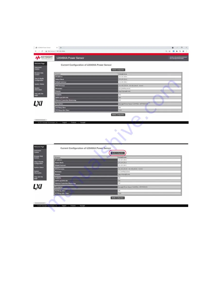
Figure 1-15
View and modify LAN configuration settings
3
Click
Modify Configuration
to edit the LAN configuration settings.
4
Enter the default password “
keysight
”.
Page 1: ...Keysight U2040 X Series Wide Dynamic Range Power Sensors Wide dynamic range power sensors for any modulated signals User s Guide...
Page 2: ...ts customarily provided to the public to use modify reproduce release per form display or disclose commercial computer software or commercial com puter software documentation No additional government...
Page 3: ...N 61326 1 Canada ICES NMB 001 Australia New Zealand AS NZS CISPR11 Environmental condition Requirement Temperature Operating condition 0 C to 55 C For U2049XA Option TVA this operating condition is ap...
Page 4: ...onfomre a la norme NMB 001 du Canada ISM GRP 1 Class A indicates that this is an Industrial Scientific and Medical Group 1 Class A product This symbol indicates the time period during which no hazardo...
Page 5: ...lectronic product in domestic household waste Product category With reference to the equipment types in the WEEE directive Annex 1 this instrument is classified as a Monitoring and Control Instrument...
Page 6: ...r sales and technical support refer to the support links on the following Keysight websites www keysight com find widedynamicsensor product specific information and support software and documentation...
Page 7: ...XA Option TVA 37 Mounting dimensions 37 Mounting procedure 38 LED Indicator Sequence During Power Up for the U2041XA 42XA 43XA 44XA Sensor 40 Other LED indicators 40 LED Indicator Sequences for the U2...
Page 8: ...rements 68 High average count reset 68 Built in radar and wireless presets 68 Gamma correction 69 S parameter correction 70 Tilt measurement 71 Exploring the U2049XA Web Interface 72 Launching the web...
Page 9: ...IP 32 Figure 1 14 U2049XA web based interface Welcome page 34 Figure 1 15 View and modify LAN configuration settings 35 Figure 1 16 Modify and renew LAN configuration settings 36 Figure 1 17 U2049XA O...
Page 10: ...Measurement Relative setting 75 Figure 2 22 Operation and Feed Setting 76 Figure 2 23 Channel Setup Normal Mode 77 Figure 2 24 Channel Setup Average Mode 77 Figure 2 25 Calibration Panel 78 Figure 2...
Page 11: ...2 Other LED indicators 41 Table 2 1 Power meter settings in the Average only mode description 57 Table 2 2 Power meter settings in the Normal mode description 59 Table 2 3 Additional Instrument Setup...
Page 12: ...12 Keysight U2040 X Series User s Guide THIS PAGE HAS BEEN INTENTIONALLY LEFT BLANK...
Page 13: ...XA 43XA 44XA sensor 21 Connect the U2049XA sensor 23 Mount the U2049XA Option TVA 37 Mounting dimensions 37 Mounting procedure 38 LED Indicator Sequence During Power Up for the U2041XA 42XA 43XA 44XA...
Page 14: ...er Ethernet PoE LAN connectivity The PoE connectivity is compliant to the IEEE 3 W 802 3af or 802 3at Type 1 standard The U2049XA is provided with two options Option 100 and Option TVA Option TVA is a...
Page 15: ...ensor LED indicator Indicates the U2041 42 43 44XA state Refer to LED Indicator Sequence During Power Up for the U2041XA 42XA 43XA 44XA Sensor on page 40 for more information RF input port for RF micr...
Page 16: ...n the operating speed is 100 Mbps No indication when the operating speed is 10 Mbps or during line isolation Amber blinking Link activity indicator Blinks when a valid link activity is detected LED in...
Page 17: ...asurement means that an instrument will output a numeric result at some rate determined by the instrument In Average mode the sensor enables a chopper amplifier circuit that allows low level signals t...
Page 18: ...be adjusted Changing the load resistor also changes the responsiveness V W of the diode detector and the video bandwidth Changing the load capacitance will affect the bandwidth but not the responsiven...
Page 19: ...damage notify the nearest Keysight Sales and Service Office Keep the damaged shipping materials if any for inspection by the carrier and a Keysight representative Standard shipped items Verify that yo...
Page 20: ...f calibration Shielded LAN cable 5 ft 1 5 m default cable length for Option 100 Thermal vacuum TVAC LAN cable 5 ft 1 5 m default cable length for Option TVA Thermal vacuum TVAC trigger cable BNC male...
Page 21: ...U2041XA 42XA 43XA 44XA sensor 1 Connect the power sensor to the PC The sensor driver is detected and installed automatically Figure 1 4 Connect the U2041XA 42XA 43XA 44XA sensor to the PC 2 Go to Star...
Page 22: ...is connected 4 When the sensor is connected go to Chapter 2 Using the U2040 X Series with the Keysight BenchVue to launch the BenchVue Power Meter application or proceed to operate the sensor via remo...
Page 23: ...allow the U2049XA to obtain an IP address The U2049XA will then try to obtain the LAN configuration using AutoIP if enabled otherwise the U2049XA will try to use the static IP set in the U2049XA If re...
Page 24: ...ection Properties and set the following properties Figure 1 7 Set automatic LAN settings on the PC 3 Go to Start All Programs IO Control to launch Keysight Connection Expert 4 Select Add LAN instrumen...
Page 25: ...instrument in Keysight Connection Expert via host name 6 Select Allow IDN Query and click Test This VISA Address to verify the U2049XA is connected Once verified click Accept 7 Alternatively you can...
Page 26: ...trument in Keysight Connection Expert via Dynamic IP 8 Click Interactive IO to verify the U2049XA is connected 9 When the U2049XA is connected go to Chapter 2 Using the U2040 X Series with the Keysigh...
Page 27: ...a private non site LAN environment Figure 1 10 Connect the U2049XA via Auto IP 1 Set up the connection as shown above 2 On your PC set the LAN settings to the automatic configuration Go to Start Contr...
Page 28: ...ick Start a Scan for connected instruments to auto locate the sensor as shown in the figure below 4 Click Interactive IO to verify the U2049XA is connected 5 When the U2049XA is connected go to Chapte...
Page 29: ...te with the instrument using the same IP address every time it is turned on Figure 1 11 Connect the U2049XA via Static IP 1 Set up the connection as shown above 2 On your PC set the LAN settings to th...
Page 30: ...onnected instruments to auto locate the sensor as shown in the figure below 4 To enable static IP click Interactive IO and send the following SCPI commands SYSTem COMMunicate LAN DHCP STATe 0 Turns of...
Page 31: ...o take effect 5 Set the PC IP address and subnet mask Go to Start Control Panel Network and Internet Network and Sharing Center Local Area Connection Properties and set the following properties Figure...
Page 32: ...a LAN instrument in Keysight Connection Expert via Static IP 7 Click Interactive IO to verify the U2049XA is connected 8 When the U2049XA is connected go to Chapter 2 Using the U2040 X Series with th...
Page 33: ...e U2049XA web based interface NOTE To revert to the Dynamic IP mode from the static IP mode you can either send the following SCPI commands SYSTem COMMunicate LAN DHCP STATe 1 SYSTem COMMunicate LAN A...
Page 34: ...1 Getting Started 34 Keysight U2040 X Series User s Guide Figure 1 14 U2049XA web based interface Welcome page 2 Click View Modify Configuration to access the LAN configuration settings...
Page 35: ...tarted 1 Keysight U2040 X Series User s Guide 35 Figure 1 15 View and modify LAN configuration settings 3 Click Modify Configuration to edit the LAN configuration settings 4 Enter the default password...
Page 36: ...s Figure 1 16 Modify and renew LAN configuration settings Configuring the LAN remotely using SCPI commands You can send SCPI commands to automatically or manually configure the LAN settings for the U2...
Page 37: ...to be mounted on a cooling plate for more effective heat dissipation when used in a TVAC chamber The cooling plate consists of four mounting threaded holes and the minimum thread height of each hole...
Page 38: ...de Mounting procedure Install the thermal interface material on to the sensor s surface 2 Briefly install the brackets 3 Stick the silver layer onto the surface Pink layer facing outward Clean the sur...
Page 39: ...Getting Started 1 Keysight U2040 X Series User s Guide 39 Place the sensor with brackets on the cooling plate 4 Align the screws to the threaded holes and tighten the screws 5...
Page 40: ...error message It is recommended to return the U2040 X Series to Keysight if this condition persists after power cycle Green Amber Red Red blinking Table 1 1 Other LED indicators Secure erase flash fo...
Page 41: ...ed Red blinking Power up LAN reset Off Normal operation Device identification LAN connection error Perform a LAN reset by power cycling the U2049XA or via its LAN reset switch It is recommended to ret...
Page 42: ...pgrade To download the latest firmware version for the U2040 X Series go to www keysight com find pm_firmware The latest firmware includes the executable file and help file for installing the Firmware...
Page 43: ...e 58 Instrument Setup tab 61 Overview of Multiple Power Sensor Operation 63 Single bench operation 63 Multiple bench operation 66 U2040 X Series Features 67 Broadband coverage for any modulated signal...
Page 44: ...e Instrument panel to start controlling the power sensor b If the sensor is found in the Keysight Connection Expert but is not shown in the BenchVue Instrument panel select the refresh icon to refresh...
Page 45: ...generator as follows Amplitude 0 dBm Frequency 1 GHz Modulation Disabled 2 Turn on the RF output of the signal generator Launch the BenchVue Power Meter application refer to page 44 By default the po...
Page 46: ...y view a Indicates acquisition of measurements in the Run mode b Indicates the measurement status c Change the title at the top of the display view Reset the displayed Minimum Maximum measured values...
Page 47: ...list and click Ok a Data preview bar b Indicates the channel name measurement number measurement type c Tools palette to provide control for the datalog chart refer to the BenchVue Power Meter help d...
Page 48: ...2 General Operating Information 48 Keysight U2040 X Series User s Guide 7 Place a marker or up to five markers on the chart by clicking to obtain the reading Marker 1...
Page 49: ...te a Trace display view by clicking 4 Perform calibration and zeroing for an accurate measurement result NOTE The default power meter mode is Average only It will change to the Normal mode when the Tr...
Page 50: ...You can set the trace scales to configure the pulse on the trace display 7 To enable gates on the trace click at the Tools Palette Measurement gate Tools Palette NOTE You can add markers or configure...
Page 51: ...e precise control of your gate parameters you can set up the gates via the Instrument Setup tab and enter a starting point and length in seconds for each of the four gate controls 8 View the power mea...
Page 52: ...2 General Operating Information 52 Keysight U2040 X Series User s Guide You can select additional pulse and gate measurements to display by clicking the Measurement Selector tab...
Page 53: ...a new Trace display view Click to create a new MultiList display view Click to assign a measurement to the selected display view Click to start or stop all assigned measurements on all display views...
Page 54: ...op the measurement acquisition Figure 2 3 Datalog settings pane Figure 2 4 Export the data log file b Save or load the instrument state of the current bench application in a proprietary format with a...
Page 55: ...ettings such as corrections frequency dependent offset gamma and S parameter alert limits recorder output trace pulse duration reference levels input impedance and trigger output For more information...
Page 56: ...s User s Guide Power meter settings in the Average only mode Figure 2 7 Power meter settings in the Average only mode Add a display view Assign a measurement to the selected view Run stop all measurem...
Page 57: ...o zero the U2040 X Series internally or externally Internal zeroing can be performed with or without the RF microwave signal present while external zeroing must be performed without any RF microwave s...
Page 58: ...uide Power meter settings in the Normal mode Figure 2 8 Power meter settings in the Normal mode Add a display view Assign a measurement to the selected view Run stop all measurements Common Normal mod...
Page 59: ...logarithmic dBm or linear Watt measurement unit Set the measurement offset factor The U2040 X Series corrects every measurement by this factor to compensate for the gain loss Enable the relative mode...
Page 60: ...g digital signal processing techniques to ensure accurate power measurement within the specified band When the video bandwidth is set to Off it removes all digital signal conditioning This provides le...
Page 61: ...ation 2 Keysight U2040 X Series User s Guide 61 Instrument Setup tab This tab provides you an option to configure additional instrument settings for your measurements as described in Table 2 3 Figure...
Page 62: ...cy related changes in the response of your test system The BenchVue Power Meter application can store 10 FDO tables with 512 frequency points each Set the gamma and S parameter corrections The BenchVu...
Page 63: ...erate multiple sensors using the BenchVue Power Meter application Single bench operation Multiple Digital Meter display views Select the instruments to use at Instrument Setup Additional Instruments A...
Page 64: ...Series User s Guide Multilist display view Select the instruments to use at Instrument Setup Additional Instruments Add a Multilist display view by clicking and selecting the measurement sources to d...
Page 65: ...s User s Guide 65 Single Trace display view with multiple traces Select the instruments to use at Instrument Setup Additional Instruments Add a Trace display view by clicking and selecting the trace s...
Page 66: ...s User s Guide Multiple bench operation Figure 2 13 Multiple bench display example Sensor number Set the sensor bench view layout Corresponds with respective sensor number Double click each connected...
Page 67: ...als with regular and time slotted or frame structure For example eight time slotted GSM bursts LTE FDD and LTE TDD frames and sub frames WCDMA frames and slots and time slotted measurements are suppor...
Page 68: ...erforming analysis simultaneously on up to 20 pulses within a single capture Individual pulse duration period duty cycle and separation positive or negative transition duration and time relative to th...
Page 69: ...o the U2040 X Series and the reflected portion will be superimposed onto Pi The nominal power Pzo the power generated after factoring in Zo may be calculated as follows Gamma correction compensates fo...
Page 70: ...as illustrated in Figure 2 15 When power is transmitted from the DUT the U2040 X Series will reflect a part of its incident wave back to the 2 port device The 2 port device will reflect this wave back...
Page 71: ...nstantaneous value reaches 10 and 90 of AM and a straight line that is the best least squares fit to the pulse in the pulse top region Trailing edge last transition amplitude AT The trailing edge ampl...
Page 72: ...ions exact navigation depends on your browser and then select LAN Settings 3 From the LAN Settings dialog select activate Bypass proxy server for local addresses exact terminology depends on your brow...
Page 73: ...setting through different HTML input types such as buttons text input radio buttons and so on Browser Web Control Displays the SCPI command interface for sending reading SCPI commands View Modify Conf...
Page 74: ...ck Enter Password A pop up window appears requesting for password 3 Enter password default password is keysight and click Submit You can view the instrument control panel of the U2049XA sensor Figure...
Page 75: ...de AUTO to the measurement signal Deselect the check box so that the measurement signal remains unchanged By default this field is disabled The corresponding SCPI command is CALCulate 1 2 3 4 RELative...
Page 76: ...ncy is set to 50 MHz The corresponding SCPI command is SENSe 1 FREQuency CW FIXed numeric_value 3 Chan Offset Sets the channel offset for U2049XA sensor Select Chan Offset dB check box for the channel...
Page 77: ...he aperture duration or measurement interval Select the unit from the drop down and enter the aperture time value By default the aperture is 50ms The corresponding SCPI command is SENSe 1 SWEep APERtu...
Page 78: ...ng mode The corresponding SCPI command is CAL ZERO TYPE INT EXT Figure 2 25 Calibration Panel System Panel The System panel allows you to select one of the following options 1 Presets This button is s...
Page 79: ...ystem panel Figure 2 27 System Panel Presets and Reset Digital Meter Display Panel In Digital Meter Display panel the following buttons are used to trigger the measurement 1 Start 2 Stop 3 Single Meas...
Page 80: ...eb Interface is supported and can be best viewed with the latest version of Google Chrome Opera and Microsoft Edge web browsers Figure 2 29 Footer System Error There is a System Error bar on the top o...
Page 81: ...namic Range Power Sensors User s Guide 3 Characteristics and Specifications NOTE For the characteristics and specifications of the U2040 X Series refer to the datasheet at http literature cdn keysight...
Page 82: ...3 Characteristics and Specifications 82 Keysight U2040 X Series User s Guide THIS PAGE HAS BEEN INTENTIONALLY LEFT BLANK...
Page 83: ...0 X Series Wide Dynamic Range Power Sensors User s Guide A Appendix Simplified Measurement Path 84 Typical Averaged Readings 85 Bandwidth Filter Shapes 87 Measurement Gates 88 Limit Checking Applicati...
Page 84: ...A Appendix 84 Keysight U2040 X Series User s Guide Simplified Measurement Path FDO Channel offset Measurement highway Measurement 1 Measurement 2 Measurement 3 Measurement 4 Gamma S parameter...
Page 85: ...m Dynamic range Number of averages Resolution setting 1 2 3 4 100 100 100 100 100 100 100 100 100 100 100 100 100 100 100 100 58 dBm 60 dBm 65 100 100 100 26 100 100 100 10 100 100 100 62 dBm 52 dBm 5...
Page 86: ...Maximum power The four resolution levels represent 1 0 1 0 01 0 001 dB respectively if the measurement suffix is dBm or dB 1 2 3 or 4 significant digits respectively if the measurement suffix is W or...
Page 87: ...x A Keysight U2040 X Series User s Guide 87 Bandwidth Filter Shapes 1 1 When the U2040 X Series frequency is set to 300 MHz Amplitude 0 3 dB Bandwidth setting Low Med High Off Frequency 5 MHz 1 5 MHz...
Page 88: ...cified by the gate are used for the measurements in that gate A system of up to four independent gates is provided Below is an example of a 4 gate setup to perform the following measurements simultane...
Page 89: ...tside these limits as shown below Table A 1 Range of values for limits Unit Maximum Minimum Default maximum Default minimum dB 200 dB 180 dB 60 dB 120 dB dBm 230 dBm 150 dBm 90 dBm 90 dBm 10 0 Z 100 0...
Page 90: ...A Appendix 90 Keysight U2040 X Series User s Guide THIS PAGE HAS BEEN INTENTIONALLY LEFT BLANK...
Page 91: ...subject to change without notice Always refer to the English version at the Keysight website for the latest revision Keysight Technologies 2015 2021 Edition 4 June 11 2021 Printed in Malaysia U2041 90...