


6
Setting up the W6602A Interposer
48
Keysight W6600A-series LPDDR4 BGA Interposers Installation Guide
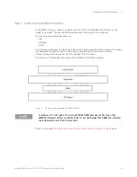
W6602A Interposer Setup - Overview
•
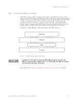
Step 1
- Solder the riser, interposer, and memory components. (See
•
Step 2
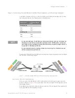
- Make clock qualifier connections. To do this, first solder the single-pin headers (shipped
with the W6602A interposer) into the clock connector(s) on top of the interposer. Then, attach the
clock qualifier connection flying leads of U4207A to these soldered single-pin headers. (See
)
•
Step 3
- Solder the retention modules to the connectorless footprints on top of the W6602A.
Attach the U4207A probes to these retention modules. (See
•
Step 4
- Connect the U4207A probe cables to the Logic Analyzer module pods. (See
CAUTION
Use ESD precautions. Electrostatic discharge can damage components on your board or in the
interposer. Use a grounded wrist strap and other ESD control measures as appropriate.
NOTE
Do not open the vacuum sealed packs of the W6602A interposer until you are ready to install
the interposer. Discard these packs once the package is opened.
WARNING
You should exercise caution when using the sharp alignment and connector pins for the
interposer and cable to avoid personal injury.
Summary of Contents for LPDDR4
Page 1: ...Keysight W6600A Series LPDDR4 BGA Interposers Installation Guide ...
Page 4: ...4 Keysight W6600A series LPDDR4 BGA Interposers Installation Guide ...
Page 8: ...8 Keysight W6600A series LPDDR4 BGA Interposers Installation Guide Contents ...
Page 10: ...1 Introduction 10 Keysight W6600A series LPDDR4 BGA Interposers Installation Guide ...
Page 78: ...Index 78 Keysight W6600A series LPDDR4 BGA Interposers Installation Guide ...
Page 79: ...Keysight W6600A series LPDDR4 BGA Interposers Installation Guide 79 ...


