


Keysight W6600A-series LPDDR4 BGA Interposers Installation Guide
53
Setting up the W6602A Interposer
6
Step 3 - Connecting the W6602A Interposer to U4207A Probes
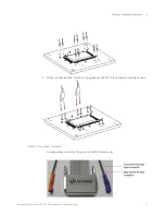
The U4207A probes attach to the interposer by soldering the E5403A retention modules to the J1
and J2 connectorless footprints on top-side of the W6602A interposer.
A kit of 5 retention modules is included in the U4207A shipment. You can order additional retention
modules kit (part number - E5403A).
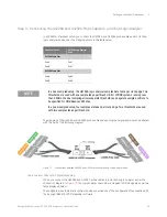
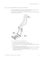
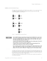
Figure 17
W6602A Interposer connected to a U4207A Probe
1 Attach the retention module to the interposer from the top.
a
Insert the retention module into the interposer noting the keying pin.
b
Solder alignment pins from the top ensuring that solder is added until a fillet is visible on the
pin.
2 Insert the U4207A probe into the retention module.
a
Ensure proper keying by aligning the Keysight logo on the probe with the one on the retention
module and place the probe end into the retention module.
b
Alternate turning each screw on the probe a little until both screws are finger tight like you
would attach a cable to your PC.
Summary of Contents for LPDDR4
Page 1: ...Keysight W6600A Series LPDDR4 BGA Interposers Installation Guide ...
Page 4: ...4 Keysight W6600A series LPDDR4 BGA Interposers Installation Guide ...
Page 8: ...8 Keysight W6600A series LPDDR4 BGA Interposers Installation Guide Contents ...
Page 10: ...1 Introduction 10 Keysight W6600A series LPDDR4 BGA Interposers Installation Guide ...
Page 78: ...Index 78 Keysight W6600A series LPDDR4 BGA Interposers Installation Guide ...
Page 79: ...Keysight W6600A series LPDDR4 BGA Interposers Installation Guide 79 ...


