Keysight E8251-60386 Installation Note Download Page 5

5

Safety Considerations

WARNING

Before you disassemble the signal generator, turn the power switch off 
and unplug the power cord. Failure to unplug the signal generator can 
result in personal injury.

CAUTION

Electrostatic discharge (ESD) can damage or destroy electronic components. All 
work on electronic assemblies should be performed at a static-safe workstation.

Check Signal Generator Functionality

Use the following procedure to confirm that the signal generator powers up and the internal check 
identifies no errors. The internal check evaluates the operation of the signal generator and returns an error 
message if it detects a problem.

NOTE

When the signal generator is first connected to ac line power, the error message 

ERROR 514, Reference Oven Cold

 occurs which causes both the 

OVEN COLD

 annunciator 

and the 

ERR

 annunciator to turn on.

After approximately five minutes, the 

OVEN COLD

 annunciator automatically clears, but the 

ERR

 annunciator remains on until all errors are cleared from the error queue.

1. Turn on the signal generator and let it warm up for at least five minutes.

2. Run the signal generator self-test by pressing 

Utility

 > 

Instrument Info/Help Mode

 > 

Self Test

Run Complete Self Test

. Upon completion a summary of the self-test will be displayed. Use the 

E8257D/67D PSG Service Guide to troubleshoot any failures detected by the test.

NOTE

Some circuits may require up to 50 minutes to warm up before passing the self-test. If 

self-tests continue to fail after 50 minutes of warm up, troubleshoot the instrument.

3. Check to see if the 

ERR

 annunciator is on.

• If  the 

ERR

 annunciator is on, review the error messages in the error queue by pressing

Utility

Error Info

. The first page of error messages in the error queue appears in the display text 

area. (Refer to the signal generator error messages document for information about each error 
message.)

After resolving all problems causing errors, press 

Clear Error Queue(s)

.

• If  the 

ERR

 annunciator is off, the signal generator functionality check has passed.

Summary of Contents for E8251-60386

Page 1: ... ness has become Keysight Technologies For more in formation go to www keysight com Keysight E8257D 67D PSG Signal Generators Add Option 1ED Type N Connector Kit Part Numbers E8251 60386 For Front RF Output E8251 60396 For Rear RF Output Installation Note Part Number E8251 90386 Printed in USA August 2014 ...

Page 2: ...o this material including but not limited to the implied warranties of merchantability and fitness for a particular purpose Keysight Technologies shall not be liable for errors contained herein or for incidental or consequential damages in connection with the furnishing performance or use of this material Copyright 2004 2014 Keysight Technologies Inc ...

Page 3: ...nerator functionality 2 Remove the outer and inner signal generator covers 3 Remove the front panel for instruments with front RF Output Connectors only 4 Install Option 1ED 5 Re assemble the signal generator 6 Verify signal generator calibration Product Affected E8257D 67D Serial Numbers All Options To Be Performed By X Agilent Technologies Service Center X Personnel Qualified by Agilent Technolo...

Page 4: ...h Needle nose pliers Table 1 E8251 60386 RF Front Output Item Quantity Description Part Number 1 1 Installation Note E8251 90386 2 1 Type N Connector Assembly E8251 60106 Table 2 E8251 60396 RF Rear Output Item Quantity Description Part Number 1 1 Installation Note E8251 90386 2 1 Type N Connector Assembly E8251 60107 ...

Page 5: ...tomatically clears but the ERR annunciator remains on until all errors are cleared from the error queue 1 Turn on the signal generator and let it warm up for at least five minutes 2 Run the signal generator self test by pressing Utility Instrument Info Help Mode Self Test Run Complete Self Test Upon completion a summary of the self test will be displayed Use the E8257D 67D PSG Service Guide to tro...

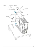
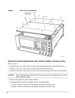
Page 6: ...ar panel feet 4 4 Remove the four bottom feet 5 from the cover by lifting the tab and sliding the foot toward the tab 5 Place the signal generator on its side 6 Tilt the signal generator forward and slide the outer cover 6 back to remove it from the frame Remove the Inner Top Cover Refer to Figure 2 1 Using a T 10 driver remove the screws 1 from the inner top cover 2 There are twelve screws for E8...

Page 7: ...7 Figure 1 Outer Cover Removal ...

Page 8: ...frame 3 Using the T 10 driver remove one screw from the top 2 and one screw from bottom 3 of the frame CAUTION Before removing the front panel from the signal generator lift and support the front of the signal generator s frame 4 Slide the front panel over the RF output connector 5 Using the needle nose pliers disconnect the following flexible cables W1 EXT 1 INPUT from the A11 Pulse Analog Modula...

Page 9: ...OUTPUT from the A11J202 W49 I IN from the A13J7 E8267D only W50 Q IN from the A13J8 E8267D only W51 DATA from the A31J500 E8267D only W52 DATA CLOCK from the A31J501 E8267D only W53 SYMBOL SYNC from the A31J502 E8267D only 6 Disconnect the A1W1 display cable from the A31 Motherboard P13 7 Disconnect the A4W1 inverter cable from the A31 Motherboard P12 8 Disconnect the W9 ribbon cable from the A31 ...

Page 10: ...output connector 2 Using the T 10 driver remove the two screws securing the connector to the rear panel of the instrument 3 Remove the old RF Output connector 4 Install the Option 1ED Type N connector by reversing the removal process steps 1 and 2 Re Assemble the Signal Generator Refer to Figure 1 and Figure 2 1 Reinstall the inner and outer instrument covers by reversing the order for removal 2 T...

Reviews: