background image

Electrostatic Discharge (ESD) precautions

Almost all electrical components can be damaged by electrostatic discharge (ESD) during handling. Component
damage can occur at electrostatic discharge voltages as low as 50 V.

The following guidelines will help prevent ESD damage during service operations:

– Disassemble instruments only in a static-free work area.

– Use a conductive work area to reduce static charges.

– Use a conductive wrist strap to reduce static charge accumulation.

– Minimize handling.

– Keep replacement parts in original static-free packaging.

– Remove all plastic, foam, vinyl, paper, and other static-generating materials from the immediate work area.

Troubleshooting

Before troubleshooting or repairing the instrument, make sure the failure is in the instrument rather than any
external connections. Also make sure that the instrument was accurately calibrated within the last year (see

Calibration Adjustment Procedures > Calibration Interval

for details).

Perform the following verifications if the unit is inoperative:

– Verify that the ac power cord is connected to the power supply.

– Verify that the front-panel power switch is depressed.

– Verify that the correct power-line fuse is installed. See

To Replace the Power Line Fuse

for details.

– Verify the power-line voltage setting.

Self-Test Procedures

A power-on self-test occurs automatically when you turn on the power supply. This limited test assures you that the
power supply is operational.

Press

Utilities

>

Test / Setup

>

Self Test

to perform the complete self-test of the power supply. It takes

approximate 2 seconds for the self-test to complete.

You can also perform a complete self-test from the remote interface, see Programming Guide for details.

– If the self-test is successful, "Self test passed" is displayed on the front panel.

– If the self-test fails, "

!Err

" is displayed on the front panel. Record the error code and message and contact Keysight

support if necessary.

– If the self-test is successful, this indicates a high chance that the power supply is operational.

Keysight E36300 Series Service Guide

13

Summary of Contents for E36300 Series

Page 1: ...Service Guide E36300 Series Programmable DC Power Supplies ...

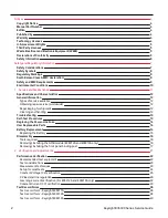
Page 2: ...nt 12 Cleaning and handling 12 Troubleshooting 13 Self Test Procedures 13 Replacing the Power Line Fuse 14 User Replaceable Parts 14 Battery Replacement 14 Replacing the Battery 15 Disassembly 16 Tools required 16 Removing Installing the GPIB module E36312A and E36313A only 16 Removing Installing the front panel binding post 17 2 Verification and Adjustments 21 Performance Verification 22 Recommen...

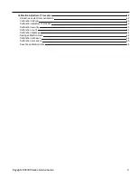
Page 3: ...42 Calibration interval 43 Calibration adjustment process 43 Calibration security 43 Calibration count 44 Calibration message 44 Saving calibration data 44 Calibration auto save 44 Calibration procedure 45 Save the calibration data 46 Keysight E36300 Series Service Guide 3 ...

Page 4: ...TTED BY APPLICABLE LAW KEYSIGHT DISCLAIMS ALL WARRANTIES EITHER EXPRESS OR IMPLIED WITH REGARD TO THIS MANUAL AND ANY INFORMATION CONTAINED HEREIN INCLUDING BUT NOT LIMITED TO THE IMPLIED WARRANTIES OF MERCHANTABILITY AND FITNESS FOR A PARTICULAR PURPOSE KEYSIGHT SHALL NOT BE LIABLE FOR ERRORS OR FOR INCIDENTAL OR CONSEQUENTIAL DAMAGES IN CONNECTION WITH THE FURNISHING USE OR PERFORMANCE OF THIS D...

Page 5: ...rcial computer software pursuant to the FAR and the DFARS and are set forth specifically in writing elsewhere in the EULA Keysight shall be under no obligation to update revise or otherwise modify the Software With respect to any technical data as defined by FAR 2 101 pursuant to FAR 12 211 and 27 404 2 and DFARS 227 7102 the U S government acquires no greater than Limited Rights as defined in FAR...

Page 6: ...ta Do not proceed beyond a CAUTION notice until the indicated conditions are fully understood and met A WARNING notice denotes a hazard It calls attention to an operating procedure practice or the like that if not correctly per formed or adhered to could result in personal injury or death Do not proceed beyond a WARNING notice until the indicated con ditions are fully understood and met 6 Keysight...

Page 7: ... injury If the instrument is to be energized via an external autotransformer for voltage reduction be certain that the auto transformer common terminal is connected to the neutral earthed pole of the AC power lines supply mains DO NOT OPERATE IN AN EXPLOSIVE ATMOSPHERE OR WET ENVIRONMENTS Do not operate the device around flammable gases or fumes vapor or wet environments DO NOT OPERATE DAMAGED OR ...

Page 8: ...on information Protective earth ground terminal Frame or chassis ground terminal Standby supply The instrument is not completely disconnected from AC mains when switch is off Alternating current AC Plus positive polarity Minus negative polarity The WARNING sign denotes a hazard It calls attention to a procedure practice or the like which if not correctly performed or adhered to could result in per...

Page 9: ...life of the product This symbol is a South Korean Class A EMC Declaration This is a Class A instrument suitable for professional use and in electromagnetic environment outside of the home The CSA mark is a registered trademark of the Canadian Standards Association South Korean Class A EMC declaration Information to the user This equipment has been conformity assessed for use in business environmen...

Page 10: ...nmental requirements for this instrument Environmental condition Requirement Temperature Operating condition 0 C to 40 C Storage condition 20 C to 70 C Humidity Operating condition Up to 80 RH at 40 C non condensing Storage condition Up to 90 RH at 65 C non condensing Altitude Up to 2000 m Pollution degree 2 10 Keysight E36300 Series Service Guide ...

Page 11: ...e Power Line Fuse User Replaceable Parts Battery Replacement Disassembly This chapter provides the specifications and service information on cleaning troubleshooting repair and replaceable parts of the E36300 Series This chapter also explains how to assemble and disassemble the E36300 Series Keysight E36300 Series Service Guide 11 ...

Page 12: ...n the original shipping carton for return shipments Repackaging for shipment Ensure the following to ship the unit to Keysight for service or repair Attach a tag to the unit identifying the owner and indicating the required service or repair Include the model number and full serial number Place the unit in its original container with appropriate packaging material Secure the container with strong ...

Page 13: ...ibration Interval for details Perform the following verifications if the unit is inoperative Verify that the ac power cord is connected to the power supply Verify that the front panel power switch is depressed Verify that the correct power line fuse is installed See To Replace the Power Line Fuse for details Verify the power line voltage setting Self Test Procedures A power on self test occurs aut...

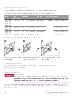
Page 14: ...s shown below Pull the fuse holder out of the power supply Remove and insert the proper fuse into the fuse holder Re insert the fuse holder into the power supply User Replaceable Parts You can find the instrument support part list at Keysight s Test Measurement Parts Catalog http www keysight com find parts Battery Replacement SHOCK HAZARD Only qualified service trained personnel who are aware of ...

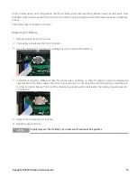
Page 15: ...ed screwdriver and carefully pry up on the side of the battery 4 Install the new battery Make sure that the positive side is facing up Place the battery under the small spring clips closest to the ribbon cable connector then push down on the opposite end of the battery to seat the bat tery see red arrow below The top of the small spring clips should be visible after the battery is seated see red c...

Page 16: ... interface RETAIN GPIB COVER PLATE After installing the GPIB option retain the cover plate for use in the event that you ever remove the GPIB option The instrument should never be connected to power or inputs on the output terminals without either the GPIB module or the cover plate securely covering the rear panel opening Make sure you turn the power supply upside down before proceeding Steps Inst...

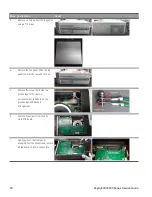
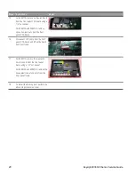
Page 17: ...dule perform the above steps in reverse order Removing Installing the front panel binding post Only qualified service trained personnel should remove and install the front panel binding post The GPIB module must be removed before you proceed to remove the front panel binding post Steps Instructions Visual 1 Remove the side trims from the front panel 2 Remove four Pozi screws from the front panel u...

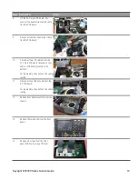
Page 18: ...ar and lift it up 5 Remove the screw that holds two ground lugs to the chassis For reassembly take note on the grounds lugs and washers arrangement 6 Remove five screws from the 25 V main PCA board 7 Gently pull out the front panel assembly from the chassis and remove all the board to board connectors 18 Keysight E36300 Series Service Guide ...

Page 19: ... main PCA board located on top and 6 V PCA board located at the bottom For reassembly take note on the cable routing 11 Disconnect one ribbon cable from the 6 V PCA board For reassembly take note on the cable routing 12 Remove front panel assembly from the chassis 13 Remove the two knobs from the front panel 14 Remove six screws from the front panel PCA board using a T8 driver Keysight E36300 Seri...

Page 20: ...rd 16 Disconnect FPC cable from the front panel PCA board and lift up the board from front frame 17 For E36311A remove the six plastic hex lock nuts from the front panel frame using a 1 2 nut socket For E36312A and E36313A remove the seven plastic hex lock nuts from the front panel frame 18 To install the binding post perform the above steps in reverse order 20 Keysight E36300 Series Service Guide...

Page 21: ...rocedures This chapter contains the performance verification procedures which verify that the E36300 Series is operating within its published specifications This chapter also provides information on adjustments performed after a performance verification fails Keysight E36300 Series Service Guide 21 ...

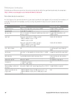
Page 22: ... load Wirewound resistor 300 W 1 6 Ω or equivalent E36311A E36312A Output 1 1 2 Ω E36313A Output 1 0 6 Ω Wirewound resistor 225 W 25 Ω or equivalent E36311A E36312A Output 2 and 3 25 Ω E36313A Output 2 and 3 12 5 Ω Ohmite MPN E300K1R6E Ohmite MPN E225K25RE LAN USB controller N A PC with Keysight Connection Expert loaded Oscilloscope Sensitivity 1 mV Bandwidth Limit 20 MHz Probe 1 1 with RF tip Key...

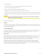
Page 23: ...ng resistor The 4 terminal current shunt is used to eliminate output current measurement error caused by voltage drops in the load leads and connections It has special current monitoring terminals inside the load connection terminals Connect the voltmeter directly to these current monitoring terminals Electronic load Many of the test procedures require the use of a variable load capable of dissipa...

Page 24: ...equired for connection between instruments A LAN or USB cable is needed for readback data The DMM measures the power supply output and the electronic load draws current from the power supply The accuracy of the current monitoring resistor must be 0 01 or better which should include any self heating effects 24 Keysight E36300 Series Service Guide ...

Page 25: ... programming accuracy Step Front Panel SCPI 5 Set the instrument settings as described in the test record form under the Voltage Programming and Readback See Test Record Forms for details VOLT 6 channel CURR 5 channel This is an example for the E36311A 6 V 5 A output 6 Enable the output by pressing ON key for the selected output OUTP ON channel 7 The output status should be CV and the output curre...

Page 26: ...d Regulation for details Enable the output 6 Operate the electronic load in constant current mode and set its current to the value in the test record form under CV Load Regulation See the Test Record Forms under Test Description of CV Load Regulation for details Check that the front panel CV annunciator of the power supply remains lit If it turns to CC or UNREG adjust the load so that the output c...

Page 27: ...he value in the test record form under CV Line Regulation See the Test Record Forms under Test Description of CV Line Regulation for details Check that the front panel CV annunciator of the power supply remains lit If it turns to CC or UNREG adjust the load so that the output current drops slightly until the CV annunciator lights up 8 Adjust the AC power source to low line voltage limit 90 VAC for...

Page 28: ...se for details Enable the output 6 Operate the electronic load in constant current mode and set its current to the value in the test record form under Transient Response See the Test Record Forms under Test Description of Transient Response for details Set the transient level to the maximum current Set the transient duty cycle to 50 and transient fre quency to 1 kHz Check that the front panel CV a...

Page 29: ...2 represent t1 and t2 The oscilloscope red trace and blue trace represent output current and output voltage trace 8 Transient response specification is met when the voltage recovers within 50 μs Keysight E36300 Series Service Guide 29 ...

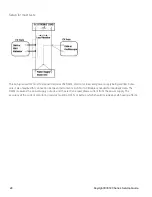
Page 30: ...ise See the Test Record Forms under CV Ripple and Noise for details 4 As shown in the figure use two BNC cables to connect the differential amplifier to the and output ter minals Each cable should be terminated by a 50 Ω resistor The shields of the two BNC cables should be con nected together Connect the differential amplifier output to the oscilloscope with a 50 Ω termination at the oscilloscope ...

Page 31: ...n on the right side Divide this value by 10 to get the CV peak to peak noise meas urement The result should not exceed the peak to peak upper limits for instrument s CV Ripple and Noise peak to peak See the Test Record Forms under CV Ripple and Noise for details 7 Disconnect the oscilloscope and connect an rms voltmeter in its place Do not disconnect the 50 Ω ter mination Divide the reading of the...

Page 32: ... a PC to control the power supply connect a LAN GPIB or USB cable from the power supply to the PC 5 Turn on the power supply using the AC line switch Low range current readback accuracy Step Front Panel SCPI 6 Set the instrument settings as described in the test record form under Low Range Current Readback Maximum Low Range Cur rent Ilow max See Test Record Forms for details VOLT 6 channel CURR 0 ...

Page 33: ...ng accuracy Step Front Panel SCPI 5 Set the instrument settings as described in the test record form under Current Programming and Readback See Test Record Forms for details VOLT 6 channel CURR 5 channel This is an example for the E36311A 6 V 5 A output 6 Enable the output by pressing the Output ON key OUTP ON channel 7 The output status should be CC and the output voltage should be close to zero ...

Page 34: ...rd form under CC Load Regulation See the Test Record Forms under Test Descrip tion of CC Load Regulation for details Check that the front panel CC annunciator of the power supply remains lit If it turns to CV or UNREG adjust the load so that the output current drops slightly until the CC annunciator lights up Record the current reading Iload by dividing the voltage reading on the DMM by the resist...

Page 35: ...or UNREG adjust the load so that the output current drops slightly until the CC annunciator lights up 7 Adjust the AC power source to low line voltage limit 90 VAC for nominal 100 VAC 104 VAC for nominal 115 VAC 194 VAC for nominal 215 VAC or 207 VAC for nominal 230 VAC Record the output current reading Ilowline by dividing the voltage reading on the DMM by the resistance of the current monitoring...

Page 36: ...put 1 Output 2 Output 3 V0 0 005 V V0 0 01 V V0 0 01 V Vmax 0 011 V Vmax 0 0225 V Vmax 0 0225 V ______________ ______________ ______________ ______________ ______________ ______________ V0 0 005 V V0 0 01 V V0 0 01 V Vmax 0 011 V Vmax 0 0225 V Vmax 0 0225 V CV Load Regulation Vload Vnoload Output 1 Output 2 Output 3 2 6 mV 4 5 mV 4 5 mV ______________ ______________ ______________ 2 6 mV 4 5 mV 4 ...

Page 37: ...004 A Imax 0 015 A Imax 0 005 A Imax 0 005 A CC Load Regulation Iload Ishort Output 1 Output 2 Output 3 750 μA 350 μA 350 μA ______________ ______________ ______________ 750 μA 350 μA 350 μA CC Line Regulation Ilowline Ihighline Output 1 Output 2 Output 3 750 μA 350 μA 350 μA ______________ ______________ ______________ 750 μA 350 μA 350 μA Test Description Instrument settings Output 1 Output 2 Ou...

Page 38: ...max 0 0044 V Vmax 0 015 V Vmax 0 015 V ______________ ______________ ______________ ______________ ______________ ______________ V0 0 002 V V0 0 005 V V0 0 005 V Vmax 0 0044 V Vmax 0 015 V Vmax 0 015 V CV Load Regulation Vload Vnoload Output 1 Output 2 Output 3 2 6 mV 4 5 mV 4 5 mV ______________ ______________ ______________ 2 6 mV 4 5 mV 4 5 mV CV Line Regulation Vlowline Vhighline Output 1 Outp...

Page 39: ..._ 750 μA 350 μA 350 μA CC Line Regulation Ilowline Ihighline Output 1 Output 2 Output 3 750 μA 350 μA 350 μA ______________ ______________ ______________ 750 μA 350 μA 350 μA Low Range Current Measurement Maximum Low Range Current measured over inter face Output 1 Output 2 Output 3 Ilow max 130 µA Ilow max 105 µA Ilow max 105 µA ______________ ______________ ______________ Ilow max 130 µA Ilow max...

Page 40: ... Voltage measured over interface Maximum Voltage measured over interface Output 1 Output 2 Output 3 Output 1 Output 2 Output 3 V0 0 003 V V0 0 005 V V0 0 005 V Vmax 0 0054 V Vmax 0 0125 V Vmax 0 0125 V ______________ ______________ ______________ ______________ ______________ ______________ V0 0 003 V V0 0 005 V V0 0 005 V Vmax 0 0054 V Vmax 0 0125 V Vmax 0 0125 V CV Load Regulation Vload Vnoload ...

Page 41: ...tput 3 0 003 A 0 002 A 0 002 A 9 991 A 1 9962 A 1 9962 A ______________ ______________ ______________ ______________ ______________ ______________ 0 007 A 0 004 A 0 004 A 10 009 A 2 0038 A 2 0038 A Current Readback Minimum Current measured over interface Maximum Current measured over interface Output 1 Output 2 Output 3 Output 1 Output 2 Output 3 I0 0 005 A I0 0 003 A I0 0 003 A Imax 0 01 A Imax 0...

Page 42: ... 0 001 A 25 V 0 001 A 25 V Current Programming Readback Maximum Current Imax 10 A 6 V 2 A 25 V 2 A 25 V CC Load Regulation Line Regulation Ripple and Noise 10 A 6 V 2 A 25 V 2 A 25 V Low Range Current Readback Maximum Low Range Current Ilow max 0 02 A 6 V 0 01 A 25 V 0 01 A 25 V Calibration Adjustment Procedures This chapter includes calibration adjustment procedures for Keysight E36300 series pow...

Page 43: ...libration See Calibration security for details 6 Take note of the security code and calibration count in the instrument s maintenance records 7 Perform the performance verification tests to verify the calibration Calibration security The instrument has a calibration passcode to prevent accidental or unauthorized calibration When you receive your power supply it is secured by a default passcode The...

Page 44: ...date the calibration due date or contact information for the person responsible for calibration The calibration message is not affected by a power cycle or RST You can only store the calibration message when the instrument is unsecured but you can execute the CALibration STRing query regardless of whether the instrument is secured A new calibration message overwrites the previous message and messa...

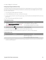
Page 45: ...nge the passcode CAL SEC CODE code Calibrate voltage Let the unit sit with output ON for one minute then connect the DMM voltage input to the power supply Step Front Panel SCPI 1 Press Perform Calibration and select the output for calibration Press Cal Volt CAL VOLT LEV MIN channel 2 Measure the output voltage low point with the DMM 3 Enter the measured value and press Next CAL VOLT reading channe...

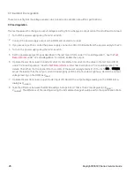
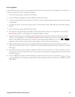
Page 46: ...ress Cal Low Curr CAL CURR LEV LOW MIN channel 2 Wait approximately 50 seconds Connect calibration resistor with the correct value as stated in the instruction shown on the display Measure the output low range current low point with the DMM 3 Enter the measured value and press Next CAL CURR LOW reading channel 4 Measure the output low range current high point with the DMM CAL CURR LEV LOW MAX chan...

Page 47: ...This information is subject to change without notice Keysight Technologies 2017 2019 Edition 3 25 November 2019 Printed in Malaysia E36311 90009 www keysight com ...

Reviews: