background image

Keysight Technologies

CX3300 Current Waveform Analyzer

Quick Operation Guide

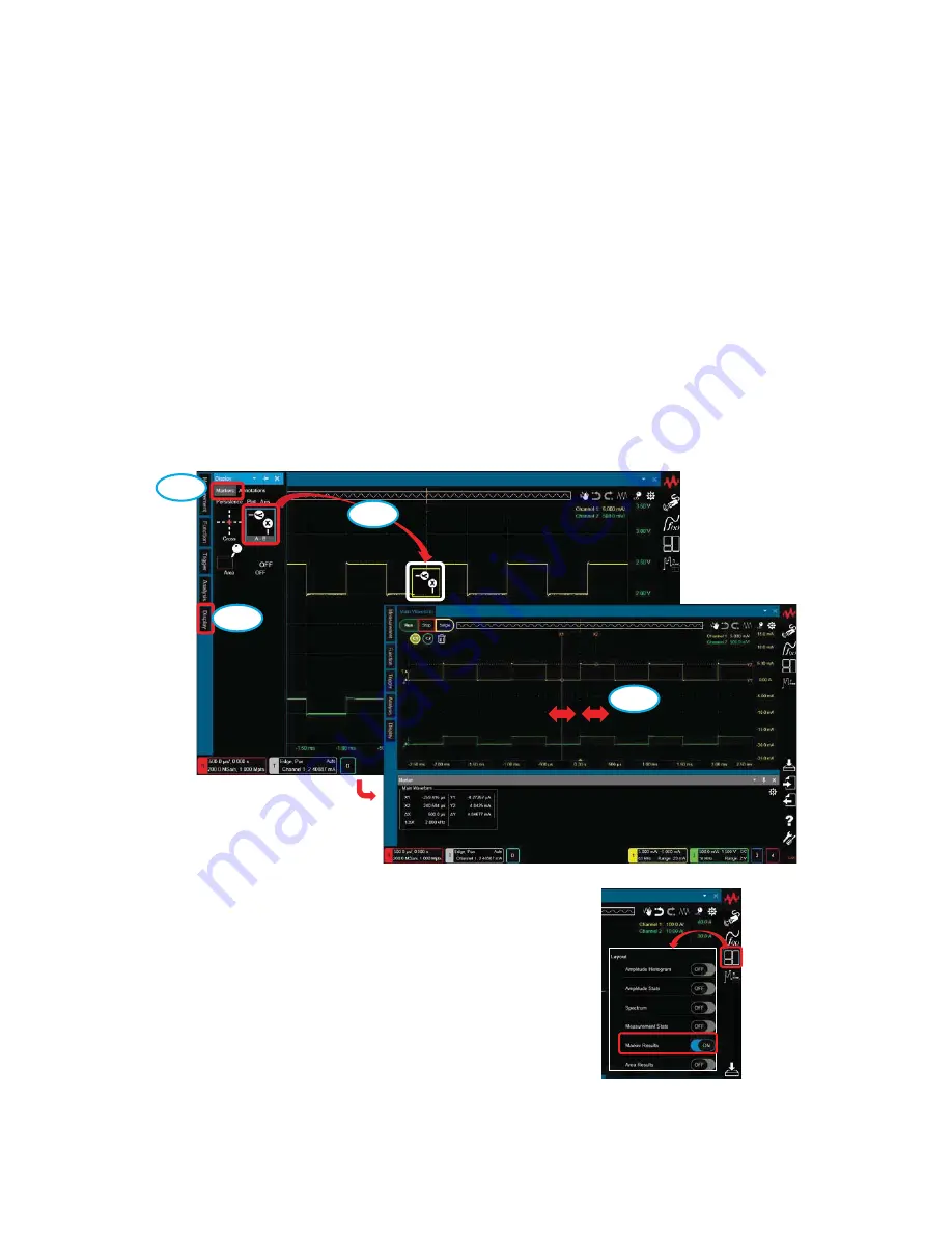
How to apply the A-B marker 

1. Turn the Marker ON.

1-1. Click “Display” on the Tool Palette.

1-2. Click “Markers”.

1-3. Drag and drop the A-B marker icon onto the target. The color of the

icon shows the target waveform.

1-4. Move X1 and X2 to the target point.

Marker Results window

1-1

Tool P

alette

1-3

1-2

1-4

Tips: You can switch the Marker Results window 

ON and OFF via Side Bar > Layout > Marker 

Results.

Side Bar

34

Summary of Contents for CX3322A

Page 1: ...Keysight Technologies CX3300 Series Device Current Waveform Analyzer CX3322A 2 Channel Model CX3324A 4 Channel Model Quick Operation Guide...

Page 2: ...sive authority by which the U S government may use modify distribute or disclose the Software The EULA and the license set forth therein does not require or permit among other things that Keysight 1 F...

Page 3: ...o use the waveform memory How to overlay multiple acquisitions How to display the secondary Y axis 3 Trigger How to set the trigger 4 Measure How to apply a Measurement Function How to apply the A B m...

Page 4: ...uick Operation Guide How to save the waveform data How to save the Waveform data in CSV format How to save the Waveform FFT data in CSV format Save Spectrum Magnitude or Spectrum Phase 1 2 3 4 5 6 7 W...

Page 5: ...ave all setting data and waveform data File Type Composite Save 1 2 3 4 5 6 Screen Capture PNG or JPEG or Bitmap Save 1 2 3 4 5 Composite Note For further details about the File Type and Format please...

Page 6: ...tion Guide How to load the data Load Select one of folders to access 1 2 3 4 5 In this case select Waveform File cxwav SelectedFile cxwav Note For further details about the File Type and Format please...

Page 7: ...form Waveform data CSV No Yes No No TSV No Waveform Yes HDF5 Yes Report Outputs the measurement and analysis result report in the dedicated style XPS Acquisition and channel setups on the summary bar...

Page 8: ...ation Guide How to save rarely occurring waveforms automatically 1 Select Utilities Configuration Auto Save Utilities 1 2 3 Change Limit Count 4 5 Blinking Checked Auto Save can be used to automatical...

Page 9: ...aved increases 2 Push the Auto Save red circle button on the lower left of the display The waveforms consistent with the trigger condition are stored up until the Limit Count set on the Configuration...

Page 10: ...Controls Change the scale Change the position Pressing it sets zero offset Horizontal Summary a b c You can change the horizontal scale and position using any of the following methods a Using the knob...

Page 11: ...sampling rate 1 Click on the Horizontal summary to open the Horizontal mini dialog box 2 Un check Automatic 3 Set the Sampling Rate Note If Auto is enabled a suitable sampling rate is selected automat...

Page 12: ...change the memory depth 1 Click on Horizontal summary to open the Timebase mini dialog box 2 Click on the at the upper right of the mini dialog box to open the Setting dialog box 3 Select Acquisition...

Page 13: ...or a 16 bit high resolution mode using the High Reso key Indicator on Horizontal Summary none 14 bit high speed mode HR 16 bit high resolution mode Note The maximum sampling rate and bandwidth is aut...

Page 14: ...waveform by either a Pressing 1 2 3 or 4 for the analog input channels OR b Clicking on the icons on the Waveform tray for the analog input channels or function waveform Vertical control keys Wavefor...

Page 15: ...tion using any of the following methods a Using the knobs on Vertical Controls b Using the Vertical mini dialog box c Using the Y Axis dialog box for fine control Vertical control keys Change the posi...

Page 16: ...ummary to open the Channel mini dialog box 2 Un check Auto 3 Select the Range Note If Auto is enabled a suitable range is selected automatically by the vertical scale setting controlled by the Vertica...

Page 17: ...ation Guide How to set the bandwidth limit 1 Click on the Channel summary to open the Channel mini dialog box 2 Click on the at the upper right of the window to open the Setting dialog box 3 Select ON...

Page 18: ...form a Null measurement DUT Mainframe Current Sensor User Calibration Null DUT VIN GND Ground lead Connection Example DUT VIN GND Ground lead Actual measurement Null measurement 3 1 Make a connection...

Page 19: ...ss Measure Click 1 3 2 The Null offset is automatically subtracted from the waveform The Null indicator turned on 4 Restore the connection then make an actual measurement again Note The Null offset is...

Page 20: ...e Interface Adapter CX1151A to the device 1 2 Execute the measurement 2 Settings 2 1 Click on the Setting icon 2 2 The Setting dialog box opens 2 3 Click on Setting Channels Skew 2 4 The Skew setup pa...

Page 21: ...ings please refer to How to change the 14 bit or 16 bit resolution Measurement range For details of settings please refer to How to change the current range Sampling rate For details of settings pleas...

Page 22: ...two kinds of zoom in functions a Zoom at single display b Anywhere Zoom a Zoom at single display a 1 Click on the Move icon to change the Zoom icon a 2 Drag the cursor until the displayed box covers t...

Page 23: ...3 4 Scale Reference Horizontal Sample 0 s 4 ms Timebase selected 4 ms 0 s selected 0 s Stretch around 0 s Stretch around the timebase center Note The setting is also retained in CX3300 power cycle and...

Page 24: ...Click on the Waveforms icon b 2 Click on the 1 zoom icon b 3 Drag the boundary line of the area Tips You can also specify the scale and position on the Axis dialog Double Click Double Click 2 Drag Mo...

Page 25: ...ory 1 Click on the Analysis icon to open the Analysis dialog box 2 Select Waveform Memories 3 Select ON 4 Select Memory X X is a number X 1 in this case 5 Press Load The waveform is loaded from Memory...

Page 26: ...multiple acquisitions 1 ON Display Persistence Infinity 1 1 Click the Display icon on the Tool Palette 1 2 Select Persistence on the Display tool palette 1 3 Drag and drop the Infinity icon on the Di...

Page 27: ...2 1 Click the Display icon on the Tool Palette 2 2 Select Persistence on the Display tool palette 2 3 Drag and drop the Normal icon on the Display tool palette onto the area of interest on the wavefor...

Page 28: ...ies CX3300 Current Waveform Analyzer Quick Operation Guide How to display the secondary Y axis 1 Select Axis in the Display Tool Pallet Then drag and drop the X1 Y1 and Y2 icon on the waveform 1 2 3 Y...

Page 29: ...ary Y Axis There are 2 ways to delete the secondary Y Axis 2 1 Drag and drop the Display Axis X1 and Y 1 icon 2 2 Double click somewhere on the screen and switch OFF the Secondary Y Axis on the Plot P...

Page 30: ...Trigger Type Default Edge 2 1 Select Trigger on the Tool Palette 2 2 Select the Trigger Type Edge in this case from the Trigger Tool Palette 2 3 Drag and drop the icon onto the target waveform The co...

Page 31: ...ger Controls OR b The Trigger Mini dialog box 4 For more detailed conditions open the Setting Trigger dialog box by either a Pressing the Menu button OR b Clicking the at the upper right of the Trigge...

Page 32: ...on the Tool Palette 1 2 Drag and drop the width icon onto the target The color of the icon shows the target waveform Keysight Technologies CX3300 Current Waveform Analyzer Quick Operation Guide How t...

Page 33: ...k Click the Measurement 1 menu 2 3 Double click the Measurements menu 2 2 You can also access the Measurement pane via Side Bar Analysis Measurement 3 Turn the measurement function off 3 2 3 1 Select...

Page 34: ...play on the Tool Palette 1 2 Click Markers 1 3 Drag and drop the A B marker icon onto the target The color of the icon shows the target waveform 1 4 Move X1 and X2 to the target point Marker Results w...

Page 35: ...isplay on the Tool Palette 3 2 Click Markers 3 3 Drag and drop the OFF icon onto the target 2 For more detailed conditions open the Markers dialog box by clicking the Setting icon on the Marker Result...

Page 36: ...alyzer Quick Operation Guide How to place pointers on waveforms 1 Select Markers in the Display Tool Pallet Then drag and drop the Cross icon on the point that you want to monitor 1 2 3 You can monito...

Page 37: ...3 ways to delete the cross hair marker 2 1 Right click the mouse on the cross hair marker and choose Delete 2 2 Click the gear icon on the upper right corner of the main screen Choose Delete Display...

Page 38: ...2 3 Click the gear icon on the upper right corner of the Marker screen Delete the marker by x click Display options ON OFF Delete all markers by x or Delete All button 1 2 38...

Page 39: ...ross hair marker is tracked as follows Right click the mouse on the cross hair marker Choose Track This cross hair marker can be tracked on the waveform in this mode This cross hair marker can NOT be...

Page 40: ...Annotation 1 Drag and drop the Display icon onto the target waveform 1 1 Click the Display icon on the Tool Palette 1 2 Click the Annotations tab 1 3 Drag and drop the Display icon on the Display tool...

Page 41: ...n delete the Annotation by right clicking on it as shown with Ch1 in the example below and selecting Delete 2 How to edit the Annotation 2 1 Select Edit by right clicking on No text 2 2 You can edit t...

Page 42: ...to apply the post filter 1 1 Click the Function icon on the Tool Palette 1 2 Select Filter on the Function tool palette 1 3 Drag and drop the Smooth 100pts icon on the Function tool palette onto the a...

Page 43: ...2 How to change the settings 2 1 Click on the Analysis icon to open the Analysis dialog box 2 2 Select Function 1 2 3 You can change the Smoothing Points Analysis 2 1 2 2 2 3 43...

Page 44: ...1 How to apply the FFT 1 1 Click the Analysis icon on the Tool Palette 1 2 Drag and drop the Spectrum icon on the Analysis tool palette onto the chosen area of interest on the waveform Note If the Zo...

Page 45: ...check the Auto box 2 3 Click this button until the Scale is 100 0KHz 3 How to adjust the chosen area of interest on the waveform The CX3300 has two ways in which to adjust the chosen area of interest...

Page 46: ...a Gating Function FFT b Waveform Zoom FFT Adjust this area Gating Horizontal Move Note The result of the FFT is changed in real time by adjusting the chosen area of interest on the waveform 46...

Page 47: ...op the Area icon on the Display tool palette onto the specified area on the waveform 1 1 1 2 1 3 There are four types of Area markers as follows Area Area width Area width and Area period Using the mo...

Page 48: ...terest Infinity Start Stop Baseline Mean The average current from Start to Stop Area Horizontal Drag Apply the Area width Area width Area period marker 1 Apply the Area width marker For example as wit...

Page 49: ...2 The result of applying the Area width Area width Area period marker Area width Area width Area period The area is automatically determined according to where you drop the marker 49...

Page 50: ...to apply the Power and Current Profiler 1 Drag and drop the Display icon onto the target waveform 1 1 Click the Analysis icon on the Tool Palette 1 2 Drag and drop the Profiler icon on the Analysis to...

Page 51: ...en the Auto Profile window 2 2 Check the Condition Set the number of levels that you want to divide the segments into for the Number of Y Levels Set a resolution that is lower than the minimum resolut...

Page 52: ...2 Perform Auto Profile Continued 2 3 Click the Perform button 2 3 52...

Page 53: ...3 Adjust the position of the line of the segments manually 3 1 3 2 3 3 3 4 Drag and drop 3 5 Reset zoom Select Zoom 2 Select the area to zoom using the mouse Select Profile Drag New 53...

Page 54: ...uide How to apply the XY analysis 1 How to apply the XY analysis 1 1 Click the Analysis icon on the Tool Palette 1 2 Drag and drop the XY icon on the Analysis tool palette on the channel set as Source...

Page 55: ...Set the target channel as Source1 and Source2 on the XY1 window 3 How to adjust the scale of the graph 3 1 Double click anywhere on the horizontal or vertical axes in the XY graph view 3 2 Un check th...

Page 56: ...c area on the waveform 4 1 Select Gating from All View Gating at the top left on the XY graph 4 2 The result of the XY graph is changed in real time by adjusting the specified area on the waveform Adj...

Page 57: ...eration Guide How to change the measurement units Clone to Ampere Hour in Area analysis 1 Select Markers in the Display Tool Pallet then drag and drop the Area icon on the interest area on the wavefor...

Page 58: ...It returns to the factory condition with Factory Default 1 1 Factory Default can be selected on the Utilities Configuration Setups window 2 Select Utilities Configuration User Preference window Utilit...

Page 59: ...tion is effective for making more accurate measurements by allowing you to perform error corrections of measurement data 1 Before starting the user calibration connect the CX1100 to the CX3300 analog...

Page 60: ...l under user calibration 2 5 Click the Execute button of the channel 2 6 The dialog box which asks you to connect the CX1100 input to the Aux Out terminal is shown If you are ready click the OK button...

Page 61: ...tion Guide How to check the firmware revisions 1 Click on the About Device Current Waveform Analyzer icon 2 The About CX3300 Device Current Waveform Analyzer window will open 3 The Firmware revisions...

Page 62: ...er to simulate the 50 MHz or 100 MHz option on the mainframe with the 200 MHz option follow the procedure below 1 Click on the Setting icon 2 The Setting dialog box opens 3 Click on Setting Channels C...

Page 63: ...nologies CX3300 Current Waveform Analyzer Quick Operation Guide Where to find the Online help 1 Click the Help icon on the Side Bar 2 Click the On line Help chm button to open the online help Help Sid...

Page 64: ...lue bar at the top of the monitor or click any other area Menu Bar Note By selecting Utilities Menu Bar from the Menu Bar it is displayed at all times By doing the same operation again you can hide th...

Page 65: ......

Page 66: ...This information is subject to change without notice Keysight Technologies 2018 Edition 1 June 2018 CX3300 90300 CX3300 90300 www keysight com...

Reviews: