


82
Chapter 3
Theory of Operation
Waveform Playback
Synchronous Triggers
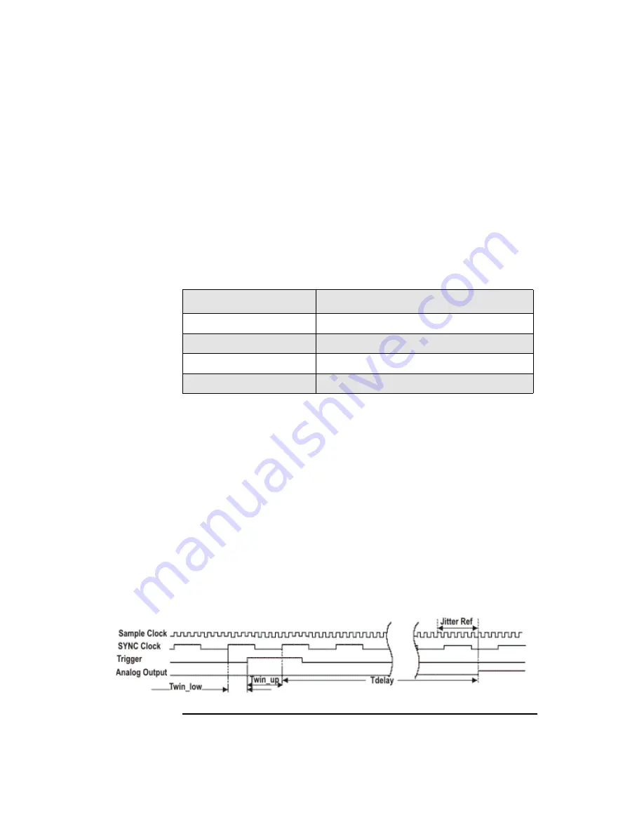
Triggers are registered into the AWG using the SYNC clock. The SYNC clock is
nominally at the sample clock frequency divided by 8. However, at lower sample
rates an internal variable modulus prescaler selects other binary divide ratios: 4, 2,
and 1. In general, the SYNC clock frequency is always in the range of 78.13 MHz to
156.25 MHz. The input clock frequency ranges and prescaler divide ratios are as
specified in
It is necessary to insure that the correct timing relationships are achieved to
guarantee consistent synchronous trigger operation. The trigger input must occur
within a valid window with respect to the SYNC clock. The window is specified by
two times: Twin_low —the minimum trigger delay after the prior SYNC clock
edge; and Twin_up — the minimum trigger setup before the next SYNC clock edge.
These are specified for the trigger input relative to the SYNC clock output. The
trigger must be a minimum of two SYNC clock cycles long. The trigger timing is
specified relative to the rising edge of the SYNC clock. The analog output from the
AWG is then produced a fixed number of sample clock cycles (plus a small fixed
propagation delay) after the first rising edge of the SYNC clock after the trigger
goes active. Since the analog output is retimed by the sample clock, the reference for
jitter measurements is the sample clock, as shown in the
. You can use an
input trigger to generate an output marker to synchronize triggers since marker
outputs are aligned with the analog output of the AWG.
Figure 3-7
Synchronous Trigger Timing Diagram
Table 3-1
Synchronous Triggers
Sample Clock Frequency
SYNC Clock Prescaler Divide Ratio
625 MHz - 1.25 GHz
8
312.5 MHz – 625 MHz
4
156.25 MHz – 312.5MHz
2
100 MHz – 156.25 MHz
1
Summary of Contents for N8241A
Page 8: ...7...
Page 9: ...8...
Page 33: ...34 Chapter 1 Introducing the N8241 2A AWGs Maintenance...
Page 64: ...Chapter 2 65 Basic Operation Using Programmatic Interfaces...
Page 65: ...66 Chapter 2 Basic Operation Using Programmatic Interfaces...
Page 76: ...Chapter 3 77 Theory of Operation Waveform Playback Figure 3 3 Waveform Play Flow Chart...
Page 91: ...92 Chapter 3 Theory of Operation Multiple Module Synchronization...
Page 109: ...110 Chapter 5 Direct Digital Synthesis Option 330 Theory of Operation Figure 5 7 DDS...


