


Disassembly 4
Series E4360 Service Guide
47
Step 5. To remove the front panel board, remove the six screws that secure the
board to the front frame assembly.
Step 6. To remove the display module, first disconnect the cable at the P1
connector and the ribbon cable at the J2 connector. Then untwist the
tabs that hold the display module to the front panel board.
Step 7. To reinstall the front panel assembly, perform the above steps in reverse
order.
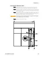
Removing/Installing the Bulk Supply
Step 1. Remove the blower cover, bulk supply cover, and interface cover as
previously described.
Step 2. Remove the output modules from the mainframe. You now have access
to two of the screws that install the bulk supplies.
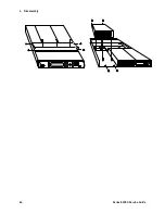
Step 3. Remove the four screws on each side of the front panel assembly that
attach the front panel assembly to the chassis. Slide the front panel
assembly forward and away from the chassis. You now have access to
the remaining screws that install the bulk supplies.
Step 4. Use a T20 driver and remove all screws that fasten the bulk supplies to
the chassis.
Step 5. Disconnect the ribbon cable that connects the interface board to the
front panel by gently lifting up on the interface board connector. Slide
the ribbon cable out so that you can access the AC and DC cable
assembly connectors.
Step 6 Disconnect the DC and AC cable assemblies and lift the bulk supplies
out of the unit. For reassembly, make a note of the color-coding of the
wires and the pins to which they are connected.
Cable assembly
Connected to Pin
Red (DC)
+48 V
Black (DC)
−
48 V
Grey (AC)
AC
Red/white (AC)
ACC
Green/yellow (AC)
ground
Step 7. To reinstall the bulk supplies, perform the above steps in reverse.
Summary of Contents for E4360 Series
Page 1: ...Service Guide Keysight Technologies Series E4360 Modular Solar Array Simulator ...
Page 2: ......
Page 6: ......
Page 10: ......
Page 40: ......
Page 44: ...4 Disassembly 44 Series E4360 Service Guide ...
Page 64: ......
Page 72: ......