background image

29

www.keyestudio.com

Step 6: Install Sensors and Boards

Summary of Contents for Ks0428

Page 1: ...e 8 Warning 8 Copyright 8 1 Introduction 9 2 Features 10 3 Specification 11 4 Product List 11 5 Assembly Guide 18 Step 1 Install Bottom Motor 18 Step 2 Install Driver Wheel 20 Step 3 Install the Batte...

Page 2: ...nstall other visions of driver 55 5 Arduino IDE Setting 58 6 Start First Program 61 7 How to Add Libraries 64 8 Projects 68 Project 1 LED Blink 69 1 Description 70 2 Specification 70 3 Equipment 71 4...

Page 3: ...ption 85 2 Specification 86 3 Equipment 86 4 Test Code 87 5 Test Result 88 6 Code Explanation 88 7 Extension Practice 89 Project 4 Servo Control 91 1 Description 91 2 Specification 93 3 Equipment 94 4...

Page 4: ...Explanation 106 9 Extension Practice 107 Project 6 IR Reception 110 1 Description 110 2 Specification 112 3 Equipment 112 4 Connection Diagram 113 5 Test Code 113 6 Test Result 115 7 Code Explanation...

Page 5: ...ive Robot to Move 133 4 Equipment 134 5 Connection Diagram 134 6 Test Code 135 7 Test Result 139 8 Code Explanation 139 9 Extension Practice 139 Project 9 8 16 LED Board 143 1 Description 143 2 Specif...

Page 6: ...172 3 Connection Diagram 172 4 Test Code 173 5 Test Result 180 Project 12 Ultrasonic Follow Tank 180 1 Description 181 2 Flow chart 182 3 Connection Diagram 182 4 Test Code 183 5 Test Result 192 Proj...

Page 7: ...by KEYES Corporation our product lines range from controller boards shields and sensor modules to smart car and complete starter kits for Arduino Raspberry Pi and BBC micro bit which designed for cus...

Page 8: ...reach of children under 7 years old please 2 This product contains conductive parts control board and electronic module Please operate according to the requirements of this tutorial Improper operatio...

Page 9: ...ch importance to STEM education Arduino is pretty notable in Maker education So what is Arduino Arduino is an open source electronics platform based on easy to use hardware and software Arduino boards...

Page 10: ...introduce the detailed knowledge about sensors and modules Simultaneously it is the best choice if you intend to obtain a DIY robot for learning programming entertainment and competition requirement 2...

Page 11: ...ent 2A Maximum power dissipation 25W T 75 Motor speed 5V 200 rpm min Motor drive mode dual H bridge drive L298P Ultrasonic induction angle 15 degrees Ultrasonic detection distance 2cm 400cm Infrared r...

Page 12: ...io com Electronic Parts Name QTY Picture 1 KEYESTUDIO V4 0 Development Board 1 2 L298P Shield 1 3 V5 Sensor Shield 1 4 HC SR04 Ultrasonic Sensor 1 5 HM 10 Bluetooth 4 0 Module 1 6 Remote Control 1 7 8...

Page 13: ...13 www keyestudio com HX 2 54 4P Female Dupont Line 1 8 9G Servo Motor 1 9 IR Receiver Module 1 10 Photocell Sensor 2 11 Red LED 1 Components 1 Acrylic Board 1 2 Tank Robot Acrylic Board 1...

Page 14: ...studio com 3 Metal Holder 4 4 L type Bracket 1 5 Tank Driver Wheel 2 6 Tank Load bearing Wheel 2 7 Caterpillar Band 2 8 Metal Motor 2 9 Plastic Platform PC 1 10 USB Cable 1m 1 11 2 54 3pin F F Dupont...

Page 15: ...ue 2 14 18650 2 Slot Battery Holder 1 15 Not included 18650 Battery 2 Tip We recommend you to purchase it on Ebay or wish Nuts Screws 1 Copper Bush 2 2 Flange Bearing 4 3 Hexagon Copper Bush M3 10MM 1...

Page 16: ...Screws M3 6MM 20 8 Inner Hexagon Screws M3 8MM 10 9 Inner Hexagon Screws M3 25MM 4 10 Inner Hexagon Screws M4 12MM 4 11 Inner Hexagon Screws M4 40MM 4 12 Inner Hexagon Screws M4 50MM 2 13 M3 Nuts 14 1...

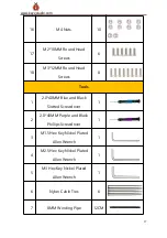
Page 17: ...Screws 8 Tools 1 2 0 40MM Blue and Black Slotted Screwdriver 1 2 2 0 40MM Purple and Black Phillips Screwdriver 1 3 M1 5 Hex Key Nickel Plated Allen Wrench 1 4 M2 5 Hex Key Nickel Plated Allen Wrench...

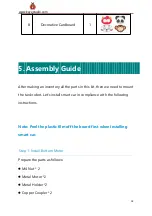
Page 18: ...to mount the tank robot Let s install smart car in compliance with the following instructions Note Peel the plastic film off the board first when installing smart car Step 1 Install Bottom Motor Prepa...

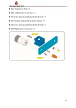
Page 19: ...estudio com Blue Supportive Parts 2 M4 12MM Inner Hex Screw 2 M1 5 Hex Key Nickel Plated Allen Wrench 1 M3 Hex Key Nickel Plated Allen Wrench 1 M2 5 Hex Key Nickel Plated Allen Wrench 1 M3 8MM Inner H...

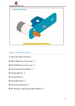
Page 20: ...ll Driver Wheel Prepare the parts as follows M4 12MM Inner Hex Screw 2 M4 50MM Inner Hex Screw 2 Tank Load bearing Wheel 2 Flange Bearing 4 Copper Bush 2 Caterpillar Band 2 M4 Self locking Nut 2 M3 He...

Page 21: ...21 www keyestudio com...

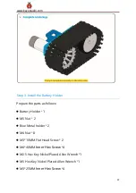
Page 22: ...older Prepare the parts as follows Battery Holder 1 M3 Nut 2 Blue Metal holder 2 M4 Nut 8 M3 10MM Flat Head Screw 2 M4 40MM Inner Hex Screw 4 M2 5 Hex Key Nickel Plated Allen Wrench 1 M3 Hex Key Nicke...

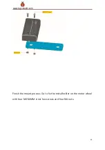
Page 23: ...23 www keyestudio com Finish the mount process Go to fix the metal holder on the motor wheel with four M4 40MM inner hex screws and four M4 nuts...

Page 24: ...24 www keyestudio com...

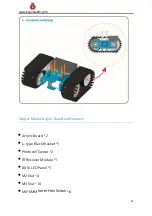
Page 25: ...25 www keyestudio com Step 4 Mount Acrylic Board and Sensors Acrylic Board 2 L type Black Bracket 1 Photocell Sensor 2 IR Receiver Module 1 8X16 LED Panel 1 M2 Nut 4 M3 Nut 10 M3 6MM Inner Hex Screw 8...

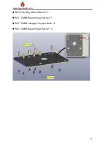
Page 26: ...26 www keyestudio com M2 5 Hex Key Allen Wrench 1 M3 12MM Round Head Screw 7 M3 10MM Hexagon Copper Bush 8 M2 10MM Round Head Screw 4...

Page 27: ...27 www keyestudio com...

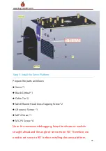
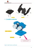
Page 28: ...Black Gimbal 1 Cable Tie 2 M2x8 Round Head Cross Tapping Screw 2 Ultrasonic Sensor 1 M2 4 Screw 1 M1 2 5 Screw 4 Note for convenient debugging keep the ultrasonic module straight ahead and the angle...

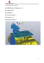
Page 29: ...29 www keyestudio com Step 6 Install Sensors and Boards...

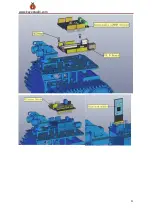
Page 30: ...30 www keyestudio com Prepare the parts as follows M3 6MM Round Head Screw 12 L298P Shield 1 V4 0 Board 1 V5 Sensor Shield 1 Screwdriver 1 Bluetooth Module 1...

Page 31: ...31 www keyestudio com...

Page 32: ...32 www keyestudio com Step 7 Hook up Guide...

Page 33: ...33 www keyestudio com...

Page 34: ...34 www keyestudio com...

Page 35: ...35 www keyestudio com Step 8 Wire Up LED Panel...

Page 36: ...36 www keyestudio com LED Panel V5 Sensor Shield GND GND VCC VCC SDA SDA SCL SCL Step 9 install all parts of Acrylic plate...

Page 37: ...37 www keyestudio com...

Page 38: ...38 www keyestudio com...

Page 39: ...39 www keyestudio com...

Page 40: ...40 www keyestudio com...

Page 41: ...41 www keyestudio com...

Page 42: ...42 www keyestudio com...

Page 43: ...43 www keyestudio com Step 10 Tank Robot Note Remove the Bluetooth module before uploading test code otherwise you will fail to upload test code...

Page 44: ...ling Arduino IDE When we get control board we need to download Arduino IDE and driver firstly You could download Arduino IDE from the official website https www arduino cc click the SOFTWARE on the br...

Page 45: ...we will show you how to download and install the windows version Arduino IDE There are two versions of IDE for WINDOWS system you can choose between the installer exe and the Zip packages For install...

Page 46: ...com You just need to click JUST DOWNLOAD 2 Keyestudio V4 0 Development Board We need to know keyestudio V4 0 development board as a core of this smart car keyestudio V4 0 development board is an Ardui...

Page 47: ...ATmega328P MCU and with a cp2102 C hip as a UART to USB converter It has 14 digital input output pins of which 6 can be used as PWM outputs 6 analog inputs a 16 MHz quartz crystal a USB connecti on a...

Page 48: ...m It contains everything needed to support the microcontroller simp ly connect it to a computer with a USB cable or power it via an ext ernal DC power jack DC 7 12V or via female headers Vin GND D C 7...

Page 49: ...ital I O Pins 6 D3 D5 D6 D9 D10 D11 Analog Input Pins 6 A0 A5 DC Current per I O Pin 20 mA DC Current for 3 3V Pin 50 mA Flash Memory 32 KB ATmega328P PU of which 0 5 KB used by bootloader SRAM 2 KB A...

Page 50: ...board the computer can recognize the hardware and automatically install the driver of CP2102 If install unsuccessfully or you intend to install manually open the device manager of computer Right click...

Page 51: ...51 www keyestudio com Click OK to enter the following page click browse my computer for updated driver software find out the installed or downloaded ARDUINO software As shown below...

Page 52: ...iver folder and you can see the driver of CP210X series chips We click Browse then find out the driver folder or you could enter driver to search in rectangular box then click next the driver will be...

Page 53: ...53 www keyestudio com Open device manager we will find the yellow exclamation mark disappear The driver of CP2102 is installed successfully...

Page 54: ...54 www keyestudio com...

Page 55: ...isions of driver If your development board is Arduino UNO board install the driver as follows Step 1 Plug in the development board click Computer Properties Device Manager you could see the unknown de...

Page 56: ...56 www keyestudio com Step 3 click browse my computer for updated driver software Step 4 find out the folder where the ARDUINO software is installed click drivers folder and tap Next...

Page 57: ...57 www keyestudio com Step 5 the driver is installed successfully The device manager shows the serial port of Arduino...

Page 58: ...58 www keyestudio com 5 Arduino IDE Setting Click icon open Arduino IDE...

Page 59: ...lect the correct Arduino board that matches the board connected to your computer Then come back to the Arduino software you should click Tools Board select the board as shown below Then select the cor...

Page 60: ...60 www keyestudio com Before uploading the program to the board let s demonstrate the function of each symbol in the Arduino IDE toolbar...

Page 61: ...etch to your Arduino board C Used to create shortcut window of a new sketch D Used to directly open an example sketch E Used to save the sketch F Used to send the serial data received from board to th...

Page 62: ...62 www keyestudio com Set board and COM port the corresponding board and COM port are shown on the lower right of IDE...

Page 63: ...63 www keyestudio com Click to start compiling the program check errors...

Page 64: ...e onboard LED lights on for 1s lights off for 1s Congratulation you finish the first program 7 How to Add Libraries What are Libraries Libraries are a collection of code that makes it easy for you to...

Page 65: ...f these additional libraries are listed in the reference Here we will introduce the most simple way for you to add libraries Step 1 After downloading well the Arduino IDE you can right click the icon...

Page 66: ...66 www keyestudio com Step 3 Next to find out the libraries of tank robot seen in the link https fs keyestudio com KS0428 you just need to replicate and paste into the libraries folder of Arduino IDE...

Page 67: ...67 www keyestudio com Download them from the link and unzip them Then add them into libraries of Arduino 1 8 13 as shown below...

Page 68: ...The whole project begins with basic program Starting from simple to complex the lessons will guide you to assemble robot car and absorb the knowledge of electronic and machinery step by step I reckon...

Page 69: ...te G marked on each sensor and module is negative pole and connected to G or GND on the sensor shield and control board V is positive pole and linked with V VCC or 5V on the sensor shield or control b...

Page 70: ...mitting diodes consist of Ga As P N chemical compound and so on The LED can flash diverse color by altering the delay time in the test code When in control power on GND and VCC the LED will be on if S...

Page 71: ...opment boards with numerous sensors However the V5 sensor shield compatible with Arduino development board address this problem perfectly Just stack V5 board on it This sensor shield can be inserted i...

Page 72: ...72 www keyestudio com Connection Diagram Seen from the above diagram LED is linked with D2...

Page 73: ...id setup pinMode 2 OUTPUT initialize digital pin 2 as an output void loop the loop function runs over and over again forever digitalWrite 2 HIGH turn the LED on HIGH is the voltage level delay 1000 wa...

Page 74: ...ooth when uploading code therefore don t link with Bluetooth module before uploading code Upload the program on the development board LED flickers with the interval of 1s 7 Code Explanation pinMode 2...

Page 75: ...We succeed to blink LED Next let s observe what LED will change if we modify pins and delay time Connection Diagram We ve altered pins and connected LED to D10 Test Code keyestudio Mini Tank Robot V2...

Page 76: ...LED off by making the voltage LOW delay 100 wait for 0 1 second The LED flickers faster through the test result therefore pins and delay time affect flash frequency Project 2 Adjust LED Brightness 1...

Page 77: ...Or what if switch among 1V 3V and 3 5V We can t change resistor constantly For this situation we need to control by PWM For the Arduino digital port voltage output there are only LOW and HIGH which co...

Page 78: ...n can t tell it neither does PWM If want different voltage need to control the ratio of 0 and 1 The more 0 1 signals output per unit time the more accurately control 2 Specification Control interface...

Page 79: ...udio com 5 Test Code keyestudio Mini Tank Robot V2 lesson 2 1 pwm http www keyestudio com int ledPin 10 Define the LED pin at D10 int value void setup pinMode ledPin OUTPUT initialize ledpin as an out...

Page 80: ...nalogWrite ledPin value LED gradually goes out delay 5 delay 5MS 6 Test Result Upload test code successfully LED gradually becomes brighter then darker like human breath rather than light on and off i...

Page 81: ...loop There is a new function in the following analogWrite We know that digital port only has two state of 0 and 1 So how to send an analog value to a digital value Here this function is needed Let s o...

Page 82: ...ying from 0 to 5V can be simulated The time turning on academically referred to as high level is called pulse width so PWM is also called pulse width modulation Through the following five square waves...

Page 83: ...mostly is used for adjusting the LED brightness or rotation speed of motor It plays vital role in controlling smart robot car I believe that you can t wait to enter next project 8 Extension Practice L...

Page 84: ...analogWrite ledPin value LED lights gradually light up delay 30 delay 30MS for value 255 value 0 value value 1 analogWrite ledPin value LED gradually goes out delay 30 delay 30MS Upload code on the de...

Page 85: ...nt light intensities We use the characteristics of the photo resistor to design the circuit and generate the photo resistor module Connecting the signal pin of photocell module to Analog port when the...

Page 86: ...6 www keyestudio com 2 Specification Resistance 5K ohm 0 5Mohm Interface Type analog Working Voltage 3 3V 5V Easy installation with screw fixing holes Pin spacing 2 54mm 3 Equipment Connection Diagram...

Page 87: ...xperiment via photoresistor connected to A1 Let s read its analog value 4 Test Code keyestudio Mini Tank Robot V2 lesson 3 1 photocell http www keyestudio com int sensorPin A1 select the input pin for...

Page 88: ...he value from the sensor Serial println sensorValue Serial port prints the resistance value delay 500 5 Test Result Upload code on development board open serial monitor check if its value diminishes w...

Page 89: ...n Serial port prints and word wrap 7 Extension Practice We ve known how to read the value of photoresistor Let s combine photoresistor with LED and view the status of LED PWM restrains the brightness...

Page 90: ...WM analog out void setup Serial begin 9600 void loop read the analog in value sensorValue analogRead analogInPin map it to the range of the analog out outputValue map sensorValue 0 1023 0 255 change t...

Page 91: ...actuator It mainly consists of housing circuit board core less motor gear and position sensor Its working principle is that the servo receives the signal sent by MCU or receiver and produces a refere...

Page 92: ...trolled by regulating the duty cycle of PWM Pulse Width Modulation signal The standard cycle of PWM signal is 20ms 50Hz Theoretically the width is distributed between 1ms 2ms but in fact it s between...

Page 93: ...cation Working voltage DC 4 8V 6V Operating angle range about 180 at 500 2500 sec Pulse width range 500 2500 sec No load speed 0 12 0 01 sec 60 DC 4 8V 0 1 0 01 sec 60 DC 6V No load current 200 20mA D...

Page 94: ...note the brown line of servo is linked with Gnd G the red line is connected to 5v V and orange line is attached to digital 9 The servo has to be connected to external power due to its high demand for...

Page 95: ...ariable of servo int pulsewidth pulse width variable of servo void setup pinMode servoPin OUTPUT set servo pin to OUTPUT procedure 0 set the angle of servo to 0 void loop for pos 0 pos 180 pos 1 goes...

Page 96: ...trol servo void procedure int myangle pulsewidth myangle 11 500 calculate the value of pulse width digitalWrite servoPin HIGH delayMicroseconds pulsewidth The duration of high level is pulse width dig...

Page 97: ...rvo The library file of servo is used in the following code 6 Test Code2 keyestudio Mini Tank Robot V2 lesson 4 2 servo http www keyestudio com include Servo h Servo myservo create servo object to con...

Page 98: ...ts 15ms for the servo to reach the position for pos 180 pos 0 pos 1 goes from 180 degrees to 0 degrees myservo write pos tell servo to go to position in variable pos delay 15 waits 15ms for the servo...

Page 99: ...e is from 0 to 180 3 read The statement to read angle of servo read the command value of write 4 Note The above written format is servo variable name specific statement for instance myservo attach 9 P...

Page 100: ...ion as well as various other applications Here we have brought the simple method to measure the distance with arduino and ultrasonic sensor and how to use ultrasonic sensor with arduino 2 Specificatio...

Page 101: ...ets obstacle and returns and the propagation speed of sound in the air is about 343m s therefore distance speed time because the ultrasonic wave emits and comes back which is 2 times of distance so it...

Page 102: ...e time from the transmission of the ultrasonic wave to the return Circuit diagram of ultrasonic sensor Trigger signals Send ultrasonic waves Send 8t 40KHz ultrasonic pulses Module gets the time gap of...

Page 103: ...103 www keyestudio com 5 Connection Diagram...

Page 104: ...shield VCC 5v V Trig 5 S Echo 4 S Gnd Gnd G 6 Test Code keyestudio Mini Tank Robot V2 lesson 5 Ultrasonic sensor http www keyestudio com int trigPin 5 Trigger int echoPin 4 Echo long duration cm inche...

Page 105: ...roseconds 2 digitalWrite trigPin HIGH delayMicroseconds 10 digitalWrite trigPin LOW Read the signal from the sensor a HIGH pulse whose duration is the time in microseconds from the sending of the ping...

Page 106: ...Upload test code on the development board open serial monitor and set baud rate to 9600 The detected distance will be displayed unit is cm and inch Hinder the ultrasonic sensor by hand the displayed...

Page 107: ...f sound The speed of sound is 343m s 0 0343 cm uS 1 29 1 cm uS Or in inches 13503 9in s 0 0135in uS 1 74in uS We need to divide the travel time by 2 because we have to take into account that the wave...

Page 108: ...k Robot V2 lesson 5 Ultrasonic LED http www keyestudio com int trigPin 5 Trigger int echoPin 4 Echo long duration cm inches void setup Serial Port begin Serial begin 9600 Define inputs and outputs pin...

Page 109: ...elayMicroseconds 10 digitalWrite trigPin LOW Read the signal from the sensor a HIGH pulse whose duration is the time in microseconds from the sending of the ping to the reception of its echo off of an...

Page 110: ...Project 6 IR Reception 1 Description There is no doubt that infrared remote control is ubiquitous in daily life It is used to control various household appliances such as TVs stereos video recorders a...

Page 111: ...te control sends out an infrared carrier signal When the IR receiver receives the signal the program will decode the carrier signal and determines which key is pressed The MCU decodes the received 01...

Page 112: ...GND It is very convenient to communicate with arduino and other microcontrollers 2 Specification Operating Voltage 3 3 5V DC Interface 3PIN Output Signal Digital signal Receiving Angle 90 degrees Fre...

Page 113: ...elopment board Attention On the condition that digital ports are not available analog ports can be regarded as digital ports A0 equals to D14 A1 is equivalent to digital 15 5 Test Code Firstly import...

Page 114: ...v irrecv RECV_PIN decode_results results decode results exist in the result of decode results void setup Serial begin 9600 irrecv enableIRIn Enable receiver void loop if irrecv decode results decode s...

Page 115: ...monitor and set baud rate to 9600 point remote control to IR receiver and the corresponding value will be shown if pressing so long the error codes will appear Below we have listed out each button va...

Page 116: ...er decoding successfully this function will come back to true and keep result in results After decoding a IR signals run the resume function and receive the next signal 8 Extension Practice We decoded...

Page 117: ...obot V2 lesson 6 2 IRremote http www keyestudio com include RremoteTank h int RECV_PIN A0 define the pin of IR receiver as A0 int LED_PIN 10 define the pin of LED int a 0 IRrecv irrecv RECV_PIN decode...

Page 118: ...lue 0xFF02FD a 0 according to the above key value press OK on remote control LED will be controlled digitalWrite LED_PIN HIGH LED will be on a 1 else if results value 0xFF02FD a 1 press again digitalW...

Page 119: ...d of customers and technology according to the need of time and situation Over the few years there are many things changed including data transmission rate power consumption with wearable and IoT Devi...

Page 120: ...od GFSK Gaussian Frequency Shift Keying Transmission power 23dbm 6dbm 0dbm 6dbm can be modified by AT command Sensitivity 84dBm at 0 1 BER Transmission rate Asynchronous 6K bytes Synchronous 6k Bytes...

Page 121: ...2 RXD serial interface receiving terminal 3 TXD serial interface transmitting terminal 4 GND Ground 5 VCC positive pole of the power source 6 EN BRK break connect it means breaking the Bluetooth conne...

Page 122: ...n serial buffer ble_val Serial read Read data from serial buffer Serial println ble_val Print There will be contradiction between serial communication of code and communication of Bluetooth when uploa...

Page 123: ...this project we send signal to control robot car via cellphone Then we need to download the APP 1 iOS system Note Allow APP to access location in settings of your cellphone when connecting to Bluetoot...

Page 124: ...location in settings of your cellphone 3 After installation open App and enable Location and Bluetooth permission 4 We take iOS version as example The operation method of Android version is almost sam...

Page 125: ...w keyestudio com 6 After connecting to HMSoft click it to get multiple options such as device information access permission general and custom service Choose CUSTOM SERVICE 7 Then pop up the following...

Page 126: ...126 www keyestudio com 8 Click Read Notify WriteWithoutResponse to enter the following page...

Page 127: ...127 www keyestudio com 9 Click Write Value appear the interface to enter HEX or Text 10 Open the serial monitor on Arduino enter a 0 or other character at Text interface...

Page 128: ...is used to judge if there is data in buffer When Serial available 0 it means that serial receives the data and can be read Serial read Read a data of a Byte in buffer of serial port for instance devi...

Page 129: ...keyestudio com keyestudio Mini Tank Robot v2 0 lesson 7 2 Bluetooth http www keyestudio com int ledpin 11 void setup Serial begin 9600 pinMode ledpin OUTPUT void loop int i if Serial available i Seri...

Page 130: ...n if i 0 digitalWrite ledpin 0 Serial println led off Click Write on APP when you enter 1 LED will be on when you input 0 LED will be off Remember to remove the Bluetooth module after finishing experi...

Page 131: ...Microelectronics It can directly drive DC motors two phase and four phase stepping motors The driving current up to 2A and output terminal of motor adopts eight high speed Schottky diodes as protectio...

Page 132: ...C5V 2 Driving part input voltage DC 7 12V 3 Logic part working current 36mA 4 Driving part working current 2A 5 Maximum power dissipation 25W T 75 6 Working temperature 25 130 7 Control signal input l...

Page 133: ...motor is D12 and speed pin is D3 D13 is the direction pin of B motor D11 is speed pin We know how to control digital ports according to the following chart PWM decides 2 motors to turn so as to drive...

Page 134: ...Equipment 5 Connection Diagram Tank Robot Motor A Motor B Forward Turn clockwise Backward Turn anticlockwise Rotate to left Turn anticlockwise Turn clockwise Rotate to right Turn clockwise Turn antic...

Page 135: ...234 The red line of right rear motor is connected to terminal 1 black line is linked with end 2 The red line of left front motor is attached to terminal 3 black line is linked with port 4 6 Test Code...

Page 136: ...t motor void setup pinMode ML_Ctrl OUTPUT define direction control pin of left motor as output pinMode ML_PWM OUTPUT define PWM control pin of left motor as output pinMode MR_Ctrl OUTPUT define direct...

Page 137: ...the direction control pin of left motor to HIGH analogWrite ML_PWM 200 set the PWM control speed of left motor to 200 digitalWrite MR_Ctrl HIGH set the direction control pin of right motor to HIGH ana...

Page 138: ...the direction control pin of left motor to LOW analogWrite ML_PWM 200 set the PWM control speed of left motor to 200 digitalWrite MR_Ctrl HIGH set the direction control pin of right motor to HIGH anal...

Page 139: ...and alternately 8 Code Explanation digitalWrite ML_Ctrl LOW the rotation direction of motor is decided by the high low level and and the pins that decide rotation direction are digital pins analogWri...

Page 140: ...13 define the direction control pin of left motor define ML_PWM 11 define the PWM control pin of left motor define MR_Ctrl 12 define the direction control pin of right motor define MR_PWM 3 define the...

Page 141: ...italWrite ML_Ctrl LOW Set direction control pin of left motor to LOW analogWrite ML_PWM 100 Set the PWM control speed of left motor to 100 digitalWrite MR_Ctrl LOW Set the direction control pin of rig...

Page 142: ...et the PWM control speed of left motor to 100 digitalWrite MR_Ctrl LOW Set direction control pin of right motor to LOW level analogWrite MR_PWM 250 Set the PWM control speed of right motor to 100 left...

Page 143: ...oject 9 8 16 LED Board 1 Description If we add a 8 16 LED board to the robot it will be amazing Keyestudio s 8 16 dot matrix can meet your requirements You can create facial emoticons patterns or othe...

Page 144: ...4Pin wiring 2 Specification Working voltage DC 3 3 5V Power loss 400mW Oscillation frequency 450KHz Drive current 200mA Working temperature 40 80 Communication method two wire bus 3 Equipment 4 8 16...

Page 145: ...scription and Communication Protocol The data of the microprocessor arduino communicates with the AiP1640 through the two wire bus interface The communication protocol diagram is shown below SCLK is S...

Page 146: ...mber 1100 0000 corresponds to the hexadecimal 0xc0 The requirement for data input is that SCL is high level when inputting data the signal on SDA must remain unchanged Only Description add 1 to the ad...

Page 147: ...be selected as shown below In the example we choose pulse width 4 16 and the hexadecimal corresponds to 1000 1010 is 0x8A 4 Introduction for Modulus Tool The online version of dot matrix modulus tool...

Page 148: ...148 www keyestudio com Open links to enter the following page The dot matrix is 8 16 in this project so set the height to 8 width to 16 as shown below...

Page 149: ...ttern As shown below press the left mouse button to select the right button to cancel draw the pattern you want click Generate and the hexadecimal data we need will be produced 5 Connection Diagram Wi...

Page 150: ...communication it can be linked with any two pins 6 Test Code The code that shows smile face keyestudio Mini Tank Robot v2 0 lesson 9 1 Matrix face http www keyestudio com the data of smiley from modul...

Page 151: ...for dot matrix display void matrix_display unsigned char matrix_value IIC_start use the function of the data transmission start condition IIC_send 0xc0 select address for int i 0 i 16 i pattern data...

Page 152: ...DA_Pin HIGH delayMicroseconds 3 digitalWrite SDA_Pin LOW delayMicroseconds 3 Convey data void IIC_send unsigned char send_data for char i 0 i 8 i Each byte has 8 bits 8bit for every character digitalW...

Page 153: ...delayMicroseconds 3 digitalWrite SCL_Pin HIGH pull up the clock pin SCL_Pin to stop transmission delayMicroseconds 3 send_data send_data 1 detect bit by bit shift the data to the right by one The sign...

Page 154: ...talWrite SCL_Pin HIGH delayMicroseconds 3 digitalWrite SDA_Pin HIGH delayMicroseconds 3 7 Test Result Wire according to connection diagram The DIP switch is dialed to right end and power on the smile...

Page 155: ...graphical code to be displayed via modulus tool Start 0x01 0x02 0x04 0x08 0x10 0x20 0x40 0x80 0x80 0x40 0x20 0x10 0x0 8 0x04 0x02 0x01 Go front 0x00 0x00 0x00 0x00 0x00 0x24 0x12 0x09 0x12 0x24 0x00 0...

Page 156: ...0x00 0x00 0x00 0x00 0x0 0 0x00 0x00 0x00 The code that the multiple patterns shift keyestudio Mini Tank Robot v2 0 lesson 9 2 Matrix loop http www keyestudio com Array used to store the data of the pa...

Page 157: ...ght 0x00 0x10 0x28 0x44 0x10 0x28 0x44 0x10 0x28 0x44 0x00 0x00 0x 00 0x00 0x00 0x00 unsigned char STOP01 0x2E 0x2A 0x3A 0x00 0x02 0x3E 0x02 0x00 0x3E 0x22 0x3E 0x00 0x 3E 0x0A 0x0E 0x00 unsigned char...

Page 158: ...ay 2000 matrix_display clear Clear the display Clear the screen delay 2000 This function is used to display of dot matrix void matrix_display unsigned char matrix_value IIC_start call the function tha...

Page 159: ...L_Pin HIGH delayMicroseconds 3 digitalWrite SDA_Pin HIGH delayMicroseconds 3 digitalWrite SDA_Pin LOW delayMicroseconds 3 Convey data void IIC_send unsigned char send_data for char i 0 i 8 i Each byte...

Page 160: ...igitalWrite SCL_Pin HIGH pull up clock pin SCL_Pin to stop transmitting data delayMicroseconds 3 send_data send_data 1 detect bit by bit so shift the data right by one The sign that data transmission...

Page 161: ...GH delayMicroseconds 3 Upload code on development board 8 16 dot matrix displays front back and stop patterns alternately Project 10 Light Follow Robot 1 Description We ve introduce how to use various...

Page 162: ...pecific logic of light following robot is shown as the table below Detection the higher the brightness the greater the value is Left photocell module left_light Right photocell module right_light If l...

Page 163: ...163 www keyestudio com We make a flow chart based on the above logic table as shown below 2 Connection Diagram...

Page 164: ...lkscreen 1234 The red line of right rear motor is connected to terminal 1 black line is linked with end 2 The red line of left front motor is attached to terminal 3 black line is linked with port 4 Le...

Page 165: ...or define light_R_Pin A2 define the pin of right photo resistor define ML_Ctrl 13 define the direction control pin of left motor define ML_PWM 11 define the PWM control pin of left motor define MR_Ctr...

Page 166: ...WM OUTPUT void loop left_light analogRead light_L_Pin right_light analogRead light_R_Pin Serial print left_light_value Serial println left_light Serial print right_light_value Serial println right_lig...

Page 167: ...650 the value detected photo resistor turn right Car_right else other situations stop Car_Stop void Car_front digitalWrite MR_Ctrl LOW analogWrite MR_PWM 200 digitalWrite ML_Ctrl LOW analogWrite ML_PW...

Page 168: ...logWrite MR_PWM 200 digitalWrite ML_Ctrl LOW analogWrite ML_PWM 200 void Car_Stop digitalWrite MR_Ctrl LOW analogWrite MR_PWM 0 digitalWrite ML_Ctrl LOW analogWrite ML_PWM 0 4 Test Result Upload code...

Page 169: ...he ultrasonic sensor detects the distance of obstacle to send signals that control the robot car Next let s show you how to make an obstacle avoidance car The specific logic of ultrasonic avoiding rob...

Page 170: ...1 unit cm Settings Servo initial angle 90 Condition 1 State a 20 Stop 1 second set the servo angle to 160 reading a1 delay 500ms set the servo angle to 20 reading a2 delay 500ms Conditi on 2 State a1...

Page 171: ...0 5s go front PWM set to 200 Conditi on 2 State a1 50 Or a2 50 Random Set the servo to 90 rotate to left PWM set to 255 for 0 5s go front PWM set to 200 Set the servo to 90 rotate to right PWM set to...

Page 172: ...172 www keyestudio com 2 Flow chart 3 Connection Diagram...

Page 173: ...Gnd G of expansion board 4 Test Code keyestudio Mini Tank Robot v2 0 lesson 11 ultrasonic_avoid_tank http www keyestudio com int random2 int a int a1 int a2 define ML_Ctrl 13 define the direction cont...

Page 174: ...in 9 servo Pin int pulsewidth the function to run motor void Car_front digitalWrite MR_Ctrl LOW analogWrite MR_PWM 200 digitalWrite ML_Ctrl LOW analogWrite ML_PWM 200 void Car_back digitalWrite MR_Ctr...

Page 175: ...digitalWrite MR_Ctrl HIGH analogWrite MR_PWM 255 digitalWrite ML_Ctrl LOW analogWrite ML_PWM 255 void Car_Stop digitalWrite MR_Ctrl LOW analogWrite MR_PWM 0 digitalWrite ML_Ctrl LOW analogWrite ML_PW...

Page 176: ...00 The function to control ultrasonic sensor float checkdistance digitalWrite Trig LOW delayMicroseconds 2 digitalWrite Trig HIGH delayMicroseconds 10 digitalWrite Trig LOW float distance pulseIn Echo...

Page 177: ...ront distance detected by ultrasonic sensor to variable a if a 20 when the front distance detected is less than 20 Car_Stop robot stops delay 500 delay in 500ms procedure 160 Ultrasonic platform turns...

Page 178: ...able a2 if a1 50 a2 50 robot will turn to the longer distance side when left or right distance is less than 50cm if a1 a2 left distance is greater than right side procedure 90 Ultrasonic platform turn...

Page 179: ...or right randomly if long random2 long 2 0 When the random number is even procedure 90 Car_left tank robot turns left delay 500 Car_front go front else procedure 90 Car_right robot turns right delay...

Page 180: ...obot car will go front Car_front go front 5 Test Result Upload code successfully DIP switch is dialed to right end and power on tank robot goes forward and automatically avoids the obstacle Project 12...

Page 181: ...low robot The ultrasonic sensor detects the distance between smart car and the obstacle to drive tank car to move The specific logic of ultrasonic follow robot is as shown below Detection Measured dis...

Page 182: ...182 www keyestudio com 2 Flow chart 3 Connection Diagram...

Page 183: ...183 www keyestudio com Wire up note 4 Test Code keyestudio Mini Tank Robot v2 0 lesson 12 ultrasonic follow tank 1 8x16 LED panel V5 Sensor Shield GND GND VCC VCC SDA SDA SCL SCL...

Page 184: ...0 0x00 0x00 0x24 0x12 0x09 0x12 0x24 0x00 0x00 0x 00 0x00 0x00 0x00 unsigned char back 0x00 0x00 0x00 0x00 0x00 0x24 0x48 0x90 0x48 0x24 0x00 0x00 0x 00 0x00 0x00 0x00 unsigned char left 0x00 0x00 0x0...

Page 185: ...efine PWM control pin of left motor define MR_Ctrl 12 define the direction control pin of right motor define MR_PWM 3 define PWM control pin of right motor define Trig 5 ultrasonic trig Pin define Ech...

Page 186: ...nMode ML_PWM OUTPUT pinMode MR_Ctrl OUTPUT pinMode MR_PWM OUTPUT void loop distance checkdistance assign the distance detected by ultrasonic sensor to distance if distance 20 distance 60 range to go f...

Page 187: ...motor running void Car_front digitalWrite MR_Ctrl LOW analogWrite MR_PWM 200 digitalWrite ML_Ctrl LOW analogWrite ML_PWM 200 void Car_back digitalWrite MR_Ctrl HIGH analogWrite MR_PWM 200 digitalWrite...

Page 188: ..._right digitalWrite MR_Ctrl HIGH analogWrite MR_PWM 200 digitalWrite ML_Ctrl LOW analogWrite ML_PWM 200 void Car_Stop digitalWrite MR_Ctrl LOW analogWrite MR_PWM 0 digitalWrite ML_Ctrl LOW analogWrite...

Page 189: ...a has 16 bits IIC_send matrix_value i data to convey patterns IIC_end end to convey data pattern IIC_start IIC_send 0x8A select pulse width4 16 control display IIC_end The condition starting to transm...

Page 190: ...italWrite SCL_Pin LOW pull down clock pin SCL Pin to change the signals of SDA delayMicroseconds 3 if send_data 0x01 set high and low level of SDA_Pin according to 1 or 0 of every bit digitalWrite SDA...

Page 191: ...void IIC_end digitalWrite SCL_Pin LOW delayMicroseconds 3 digitalWrite SDA_Pin LOW delayMicroseconds 3 digitalWrite SCL_Pin HIGH delayMicroseconds 3 digitalWrite SDA_Pin HIGH delayMicroseconds 3 end d...

Page 192: ...t checkdistance digitalWrite Trig LOW delayMicroseconds 2 digitalWrite Trig HIGH delayMicroseconds 10 digitalWrite Trig LOW float distance pulseIn Echo HIGH 58 20 58 20 that is 2 29 1 58 2 delay 10 re...

Page 193: ...ic fan and some household appliances In this project we will make an IR remote smart car And we ve known every key value on IR remote control Thus we could control smart car via and display the patter...

Page 194: ...front icon FFA857 Go back PWM set to 200 8X16 LED panel shows back icon FF22DD Turn left 8X16 LED panel shows leftward icon FFC23D Turn right 8X16 LED panel shows rightward icon FF02FD Stop 8X16 LED p...

Page 195: ...of 8x16 LED panel are respectively linked with GND VCC SDA SCL And and S of IR receiver module are attached to G GND V VCC and A0 on sensor shield On the condition of insufficient digital ports the a...

Page 196: ...irrecv to A0 decode_results results long ir_rec save the IR value received Array used to store the data of the pattern can be calculated by yourself or obtained from the modulus tool unsigned char st...

Page 197: ...00 unsigned char STOP01 0x2E 0x2A 0x3A 0x00 0x02 0x3E 0x02 0x00 0x3E 0x22 0x3E 0x00 0x3E 0x0A 0x0E 0x00 unsigned char clear 0x00 0x00 0x00 0x00 0x00 0x00 0x00 0x00 0x00 0x00 0x00 0x00 0x00 0x00 0x00 0...

Page 198: ...ze the IR reception library pinMode ML_Ctrl OUTPUT pinMode ML_PWM OUTPUT pinMode MR_Ctrl OUTPUT pinMode MR_PWM OUTPUT pinMode SCL_Pin OUTPUT pinMode SDA_Pin OUTPUT matrix_display clear Clear Screen ma...

Page 199: ...O MITSUBISHI SAMSUNG LG WHYNTER if results decode_type 1 results decode_type 13 type typelist results decode_type Serial print IR TYPE type Serial println ir_rec HEX irrecv resume if ir_rec 0xFF629D G...

Page 200: ...FC23D Robot car turns right Car_T_right matrix_display right Display right turning image if ir_rec 0xFF02FD Robot car stops Car_Stop matrix_display STOP01 show stop image if ir_rec 0xFF30CF robot car...

Page 201: ...i 0 i 50 i i 1 pulsewidth myangle 11 500 digitalWrite servoPin HIGH delayMicroseconds pulsewidth digitalWrite servoPin LOW delay 20 pulsewidth 1000 Dot Matrix this function is used for dot matrix dis...

Page 202: ...splay control set pulse width to 4 16 IIC_end The condition starting to transmit data void IIC_start digitalWrite SCL_Pin HIGH delayMicroseconds 3 digitalWrite SDA_Pin HIGH delayMicroseconds 3 digital...

Page 203: ...01 set high and low level of SDA_Pin according to 1 or 0 of every bit digitalWrite SDA_Pin HIGH else digitalWrite SDA_Pin LOW delayMicroseconds 3 digitalWrite SCL_Pin HIGH pull up clock pin SCL_Pin to...

Page 204: ...ayMicroseconds 3 digitalWrite SCL_Pin HIGH delayMicroseconds 3 digitalWrite SDA_Pin HIGH delayMicroseconds 3 the function to run motor void Car_front digitalWrite MR_Ctrl LOW analogWrite MR_PWM 200 di...

Page 205: ...R_Ctrl LOW analogWrite MR_PWM 255 digitalWrite ML_Ctrl HIGH analogWrite ML_PWM 255 void Car_right digitalWrite MR_Ctrl HIGH analogWrite MR_PWM 255 digitalWrite ML_Ctrl LOW analogWrite ML_PWM 255 void...

Page 206: ...l LOW analogWrite ML_PWM 180 void Car_T_right digitalWrite MR_Ctrl LOW analogWrite MR_PWM 180 digitalWrite ML_Ctrl LOW analogWrite ML_PWM 255 5 Test Result Upload code successfully and power on the sm...

Page 207: ...ke a Bluetooth remote smart car In the experiment we default the HM 10 Bluetooth module as a Slave and the cellphone as a Host keyes BT car is an APP rolled out by keyestudio team You could control th...

Page 208: ...ni Tank Robot v2 0 lesson 14 1 bluetooth test http www keyestudio com char ble_val character variables used to save the value of Bluetooth reception void setup Serial begin 9600 void loop if Serial av...

Page 209: ...intln ble_val print out Pull off the Bluetooth module upload test code reconnect Bluetooth module open serial monitor and set baud rate to 9600 Point at Bluetooth module and press keys on APP the corr...

Page 210: ...210 www keyestudio com 3 Connection Diagram...

Page 211: ...211 www keyestudio com Wiring Attention 8x16 LED panel Expansion Board GND GND VCC VCC SDA SDA SCL SCL Insert Bluetooth module vertically you don t need to attach to its STATE and BRK pins...

Page 212: ...com Array used to store the data of pattern can be calculated by yourself or obtained from the modulus tool unsigned char start01 0x01 0x02 0x04 0x08 0x10 0x20 0x40 0x80 0x80 0x40 0x20 0x10 0x 08 0x04...

Page 213: ...0x00 0x 3E 0x0A 0x0E 0x00 unsigned char clear 0x00 0x00 0x00 0x00 0x00 0x00 0x00 0x00 0x00 0x00 0x00 0x00 0x 00 0x00 0x00 0x00 define SCL_Pin A5 Set clock pin to A5 define SDA_Pin A4 Set data pin to A...

Page 214: ...y clear Clear the display matrix_display start01 display start pattern pinMode ML_Ctrl OUTPUT pinMode ML_PWM OUTPUT pinMode MR_Ctrl OUTPUT pinMode MR_PWM OUTPUT void loop if Serial available bluetooth...

Page 215: ...reak case L left turning instruction Car_left matrix_display left show left turning sign break case R right turning instruction Car_right matrix_display right display right turning sign break case S s...

Page 216: ...has 16 bits IIC_send matrix_value i data to convey patterns IIC_end end to convey data pattern IIC_start IIC_send 0x8A display control set pulse width to 4 16 IIC_end The condition starting to transm...

Page 217: ...SCL_Pin LOW pull down clock pin SCL Pin to change the signals of SDA delayMicroseconds 3 if send_data 0x01 set high and low level of SDA_Pin according to 1 or 0 of every bit digitalWrite SDA_Pin HIGH...

Page 218: ...oid IIC_end digitalWrite SCL_Pin LOW delayMicroseconds 3 digitalWrite SDA_Pin LOW delayMicroseconds 3 digitalWrite SCL_Pin HIGH delayMicroseconds 3 digitalWrite SDA_Pin HIGH delayMicroseconds 3 the fu...

Page 219: ...digitalWrite ML_Ctrl HIGH analogWrite ML_PWM 200 void Car_left digitalWrite MR_Ctrl LOW analogWrite MR_PWM 255 digitalWrite ML_Ctrl HIGH analogWrite ML_PWM 255 void Car_right digitalWrite MR_Ctrl HIGH...

Page 220: ...rite ML_Ctrl LOW analogWrite ML_PWM 0 void Car_T_left digitalWrite MR_Ctrl LOW analogWrite MR_PWM 255 digitalWrite ML_Ctrl LOW analogWrite ML_PWM 180 void Car_T_right digitalWrite MR_Ctrl LOW analogWr...

Page 221: ...car to move by Bluetooth App Press tank robot goes forward click smart car goes back press button tank robot turns left click robot turns right hold it stops Click to enable gravitational control tap...

Page 222: ...s projects the tank car only performs single function however in this lesson we integrate all of function to control smart car via Bluetooth control Here is a simple flow chart of multi purpose robot...

Page 223: ...223 www keyestudio com Attention Confirm that every component is connected...

Page 224: ...224 www keyestudio com Wire up Guide 8x16 LED panel Expansion Board GND GND VCC VCC SDA SDA SCL SCL Ultrasonic Module VCC 5v V Trig 5 S Echo 4 S Gnd Gnd G...

Page 225: ...225 www keyestudio com Servo Motor Brown Wire Gnd G Red Wire 5v V Orange Wire 9...

Page 226: ...226 www keyestudio com Bluetooth Module RXD TX TXD RX GND GND VCC VCC No need to attach to STATE and BRK pins...

Page 227: ...227 www keyestudio com IR Receiver Module Sensor Shield G GND V VCC S A0...

Page 228: ...228 www keyestudio com 3 Test Code Left photo resistor Sensor Shield G GND V VCC S A1 Right Photo resistor Sensor Shield G GND V VCC S A2...

Page 229: ...10 0x20 0x40 0x80 0x80 0x40 0x20 0x10 0x 08 0x04 0x02 0x01 unsigned char front 0x00 0x00 0x00 0x00 0x00 0x24 0x12 0x09 0x12 0x24 0x00 0x00 0x 00 0x00 0x00 0x00 unsigned char back 0x00 0x00 0x00 0x00 0...

Page 230: ...efine direction control pin of left motor define ML_PWM 11 define PWM control pin of left motor define MR_Ctrl 12 define direction control pin of right motor define MR_PWM 3 define PWM control pin of...

Page 231: ..._Pin A2 define the pin of right photo resistor sensor int left_light int right_light char bluetooth_val save the value of Bluetooth reception int flag flag variable it is used to entry and exist funct...

Page 232: ...ix_display clear Clear the display matrix_display start01 display start pattern pinMode light_L_Pin INPUT pinMode light_R_Pin INPUT void loop if Serial available bluetooth_val Serial read Serial print...

Page 233: ...trix_display left show left turning pattern break case R right turning instruction Car_right matrix_display right show right turning pattern break case S stop instruction Car_Stop matrix_display STOP0...

Page 234: ...oid flag 0 the design that enter obstacle avoidance function while flag 0 random2 random 1 100 a checkdistance assign the front distance detected by ultrasonic sensor to variable a if a 20 when the fr...

Page 235: ...a2 checkdistance assign the right distance detected by ultrasonic sensor to variable a2 if a1 50 a2 50 robot will turn to the longer distance side when left or right distance is less than 50cm if the...

Page 236: ...s right delay 500 Car_front go forward else both distance on two side is greater than or equal to 50cm turn randomly if long random2 long 2 0 when the random number is even procedure 90 Car_left robot...

Page 237: ...tance is greater than or equal to 20cm robot car will go front Car_front go forward receive the Bluetooth value to end the obstacle avoidance function if Serial available bluetooth_val Serial read if...

Page 238: ...sensor to distance if distance 20 distance 60 the range to go front Car_front else if distance 10 distance 20 the range to stop Car_Stop else if distance 10 the range to go back Car_back else other s...

Page 239: ...lWrite Trig HIGH delayMicroseconds 10 digitalWrite Trig LOW float distance pulseIn Echo HIGH 58 00 58 20 means 2 29 1 58 2 delay 10 return distance The function to control servo the function controlli...

Page 240: ...light analogRead light_R_Pin if left_light 650 right_light 650 the value detected by photo resistor go forward Car_front else if left_light 650 right_light 650 the value detected by photo resistor tur...

Page 241: ...uetooth_val S flag 1 Dot Matrix this function is used for dot matrix display void matrix_display unsigned char matrix_value IIC_start IIC_send 0xc0 Choose address for int i 0 i 16 i pattern data has 1...

Page 242: ...econds 3 digitalWrite SDA_Pin HIGH delayMicroseconds 3 digitalWrite SDA_Pin LOW delayMicroseconds 3 convey data void IIC_send unsigned char send_data for char i 0 i 8 i each byte has 8 bits digitalWri...

Page 243: ...ull up clock pin SCL_Pin to stop transmitting data delayMicroseconds 3 send_data send_data 1 detect bit by bit so move the data right by one The sign that data transmission ends void IIC_end digitalWr...

Page 244: ..._front digitalWrite MR_Ctrl LOW analogWrite MR_PWM 200 digitalWrite ML_Ctrl LOW analogWrite ML_PWM 200 void Car_back digitalWrite MR_Ctrl HIGH analogWrite MR_PWM 200 digitalWrite ML_Ctrl HIGH analogWr...

Page 245: ...nalogWrite MR_PWM 255 digitalWrite ML_Ctrl LOW analogWrite ML_PWM 255 void Car_Stop digitalWrite MR_Ctrl LOW analogWrite MR_PWM 0 digitalWrite ML_Ctrl LOW analogWrite ML_PWM 0 void Car_T_left digitalW...

Page 246: ...will fail to upload test code Reconnect Bluetooth module after uploading test code Upload test code successfully insert Bluetooth module power on and connect to Bluetooth The tank robot can show disti...

Page 247: ...247 www keyestudio com 9 Resources Wiki page https wiki keyestudio com Main_Page Official website https keyestudio com Assembly Video Link http video keyestudio com ks0428...

Reviews: