


6
7
EDID Control
The KD-HD16x16ProK has a built-in library of 15 EDID settings and the ability to copy EDID data
from the display connected to output 1.
›
To copy EDID from output 1, press “
EDID
”
➔
Output 1 button
›
To select a default EDID, press “
EDID
”
➔
input button
(1-15)
that corresponds to the default
EDID you want to set. See the chart below for a list of EDID library settings.
›
Note: The default EDID is
No. 4: 1080p, 2ch. Audio
1
1080i, 2CH AUDIO
10
4Kx2K, 2CH AUDIO
2
1080i, DOLBY/DTS 5.1
11
4Kx2K, DOLBY/DTS 5.1
3
1080i, HD AUDIO
12
4Kx2K, HD AUDIO
4
1080p, 2CH AUDIO (DEFAULT)
13
1280x1024 DVI
5
1080p, DOLBY/DTS 5.1
14
1920x1080 DVI
6
1080p, HD AUDIO
15
1920x1200 DVI
7
3D, 2CH AUDIO
* EDID (Extended display identification data) is a data
structure provided by a display to describe its capabilities
to a source device
8
3D, DOLBY/DTS 5.1
9
3D, HD AUDIO
Output Disable/Enable
The “
Output Disable
” button serves two purposes: disabling unused output(s) and shutting the
LCD screen.
›
To toggle the LCD on/off, press the “
Output Disable
” button
›
To disable an output, press the desired output button
➔
press “
Output Disable
”
»
A disabled output is indicated by “00” on the LCD screen
›
To disable all outputs, press “
All Out
”
➔
”
Output Disable
”
›
To enable an output, simply send it a switching command
IR Remote Operation
The IR remote control mimics the functions of the front panel buttons.
To use the IR remote control, follow the chart below for button
functions and execute functions the same way you would via
the front panel buttons.
Front Panel Function
Remote Button
Exit
POWER
Output Disable
OFF
All Out
ALL
Unit Info
ID
Memory Store
STO
Memory Recall
RCL
»
OSD, SCAN, UP Arrow, DOWN Arrow, AUDIO, VIDEO, and “+10” have no function
Example:
To set output 16 to input 05, press OUT 1, OUT 6, IN 0, IN 5 or OUT 1, OUT 6, IN 5
(note: “OUT 0” and “IN 0” button presses may be omitted)
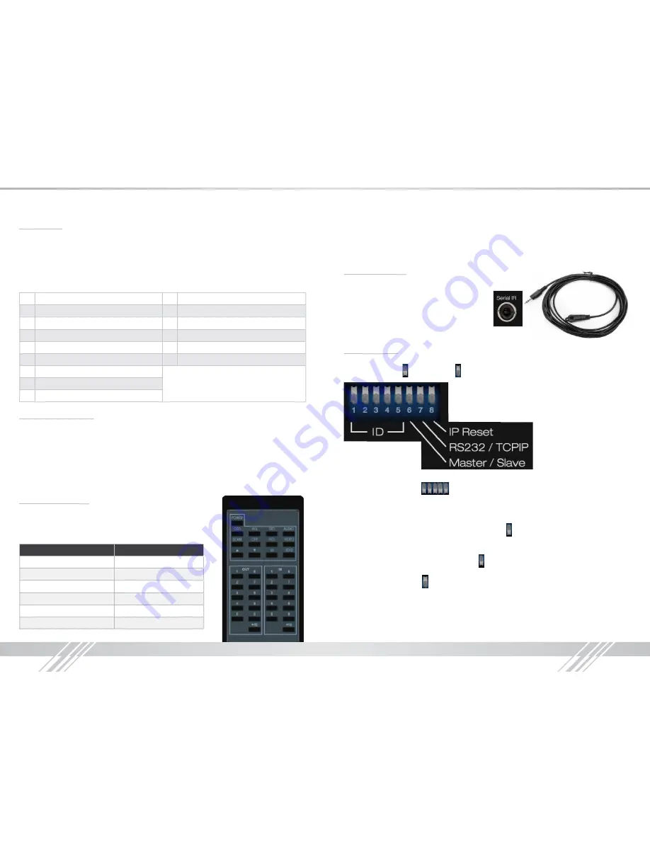
Serial IR Operation
The unit may also be controlled via the Serial IR
interface. You must use the supplied Serial IR
cable (pictured to the right). This cable connects
to the “Serial IR” input port on the back of the unit.
The other end of the cable contains an IR receiver,
to which you can send IR control signals.
8 Pin Dip Switch
There is an 8 pin dipswitch on the back right of the unit.
Flipping a pin down is “ON” and up is “OFF”.
›
Pins 1-5: Configure the Device ID
»
Single Unit: 00000 (
= Default ) (ON=0, Off=1)
»
All other configurations are used for multi-unit control/configuration
›
Pin 6: RS-485 Master/Slave Configuration
»
Off: RS-485 master; RS-232 and TCP/IP disabled
»
On: RS-485 slave; RS-232 and TCP/IP enabled ( =Default)
›
Pin 7: RS-232 or TCP/IP port control selection
»
Off: TCP/IP enabled; RS-232 disabled
»
On: RS-232 enabled; TCP/IP disabled ( =Default)
›
Pin 8: TCP/IP Reset
»
Off: TCP/IP normal ( =Default)
»
On: TCP/IP reset


