6.7.3
Air - Gas Assembly
WD420/3/2007
Chapter 6 : Fault Finding
The Keston Qudos 28s & Qudos 28sP Boilers
Installation & Servicing Instructions
Page : 41
Page 1: ...930 17 Qudos 28sP GC No 41 930 18 These instructions must be left either with the user or next to the site gas meter 34 West Common Road Hayes Bromley Kent BR2 7BX Tel 44 0 20 8462 0262 Fax 44 0 20 84...
Page 2: ...Data 2 5 Optional Accessories 2 6 Performance Data 3 BOILER LOCATION 3 1 Dimensions Minimum Clearances 3 2 Service Connections 3 3 Position 3 4 Electrical 3 5 Boiler Size Selection 3 6 Gas Supply 3 7...
Page 3: ...strated Wiring Diagram 6 7 Exploded Assembly Diagrams 7 SERVICING 7 1 Pre Service Checks 7 2 Recommended Routine Service 8 REPLACEMENT OF PARTS 8 0 General 8 1 Precautions 8 2 Access 8 3 Replacement P...
Page 4: ...ap fixing washers 2 Inside accessories bag Condensate Trap Gasket 1 Inside accessories bag 50 mm muPVC Pipe 2 Inside boiler case 50 mm muPVC Elbow 2 Inside boiler case Document List Item Quantity Loca...
Page 5: ...orners of the boiler back plate When lifting this appliance the back should be kept straight at all times Avoid twisting at the waist reposition the feet instead Avoid upper body bending when holding...
Page 6: ...mp cloth and finish with a dry cloth 1 3 BOILER SETUP OPERATION Check that the gas supply from the gas meter is turned on Switch on the electrical supply to the boiler The display will now run through...
Page 7: ...fault Display The above is an abbreviated list of possible error codes If the code is not in the list above consult a CORGI registered engineer A full list of codes can be found in Chapter 6 of this m...
Page 8: ...red in the event of any warranty work being required There is also Service Interval Record Chapter 10 to be completed after each annual service visit These forms Chapter 10 should be kept in a safe pl...
Page 9: ...ptional legionella prevention function Further the Qudos 28s is developed with the concept that the gas boiler in the modern home is often supplemented by alternative or renewable energy sources As a...
Page 10: ...lastic pipe Gas is mixed with combustion air at the inlet to the fan The gas flow is automatically regulated by the gas valve according to the air flow generated by the fan The gas and air are thoroug...
Page 11: ...compatible energy management systems An optional Keston room controller can be connected which will provide enhanced controls such as room compensation to further increase efficiency and comfort leve...
Page 12: ...2 Air Supply BS 5482 1 Domestic Propane and Butane Burning Installations BS 7074 1 Expansion Vessels BS 7593 Treatment of Water in Hot Water Central Heating Systems BS 7671 Requirements for Electrica...
Page 13: ...utlet and Air Intake Length m 120 2 5 OPTIONAL ACCESSORIES A range of accessories are available from Keston Boilers Ltd to compliment an installation Terminal wall sealing collars are available to mak...
Page 14: ...2 General Instruction The Keston Qudos 28s Qudos 28sP Boilers Installation Servicing Instructions Page 9 Qudos 28s Qudos 28sP Nat Gas G20 LPG G31 Min Input Gross CV kW Btu h 7 8 26 600 7 6 26 000 Max...
Page 15: ...he industry wide Benchmark initiative Qudos 28S boiler manual includes Gas Boiler Commissioning Checklist Chapter 10 This form should be completed by your installer at the end of the installation and...
Page 16: ...in any room or internal space although particular attention is drawn to the requirements of the current IEE Wiring Regulations and in Scotland the electrical provisions of the Building Regulations ap...
Page 17: ...refore accept up to TWO switched live 230VAC signal inputs such as heating and hot water or radiators and underfloor heating zones Alternatively a Keston Room Controller can be connected directly via...
Page 18: ...nsation Ext Sensor A Keston outside temperature sensor may be connected as an option The boiler will automatically detect this connection and will operate on a weather compensation basis when receivin...
Page 19: ...length of run from the meter to the boiler at a supply rate of 28 4kW i e a natural gas supply should be considered to be a minimum of 22mm diameter reducing to 15mm at the boiler If gas runs greater...
Page 20: ...tal Water Content of system in excess of 125 litres 1 0 bar Vessel charge initial system pressure 3 0 bar Safety Valve Setting k The boiler is supplied with an integral expansion vessel of 8l capacity...
Page 21: ...e It is advisable to incorporate a boiler by pass in the system especially if thermostatic radiator valves are used The flow return differential should be 10o C to 20o C To comply with the Building Re...
Page 22: ...a function Refer to Chapter 4 for more detail 3 7 5 Filling The System The system should be filled using a G24 approved filling loop The system pressure should be set to between 1 0 and 2 0 bar To dis...
Page 23: ...0m 1 0m 37 0m Flue outlet uses one 92 5o sweep elbow Hence maximum length permissible i e c d in figure 3 8 2 20 0m 1 0 m 19 0m 3 8 3 Slope Horizontal flue outlet pipework MUST slope at least 2 degre...
Page 24: ...car port not recommended 1 200 1 200 I From terminal facing a terminal 100 600 H From surface or boundary facing a terminal 100 200 G Above ground or balcony or roof 50 200 F From internal or external...
Page 25: ...th facility to connect to a drain point underneath the appliance The condensate trap is packed loose with the appliance and MUST be fitted BEFORE firing the appliance Use only plastic piping and do no...
Page 26: ...cleaning and testing a Lift and locate the boiler onto the stud and the two locating pegs protruding from the wall bracket lift the boiler via the back frame only b Lower the boiler for hanging on th...
Page 27: ...and make good all holes wall sealing collars are available to make good hole areas on the wall face part number C 08 0 00 07 0 g Support any pipes whose route could be displaced either of its own acc...
Page 28: ...ectrical supply must be as specified in Chapter 3 Section 3 4 Electrical Supply WARNING THIS APPLIANCE MUST BE EARTHED 2 All external controls and wiring must be suitable for mains voltage Supply wiri...
Page 29: ...2 1 CH1 1 0 10V 0v 2 SENSOR 1 2 SENSOR 2 SENSOR 1 1 2 NO OPEN SOL DHW TS FLOW ANALOG DEMAND EXTERNAL SENSOR MAIN SUPPLY SOLAR PUMP CH DEMAND 1 N N SL1 SL2 E L LOCKOUT COM NO 2 C 10C 0 09 00 0 EXTERNA...
Page 30: ...ux or solder the system must be flushed cold again before proceeding Reduce the pressure to the Initial System Design Pressure Vent the system Gas Supply The complete gas installation up to the boiler...
Page 31: ...s inlet pressure is satisfactory set the gas pressure check the gas input Full details of this procedure are given in Section 5 9 Timing The Gas Meter Combustion Testing It is advisable on all install...
Page 32: ...ushed cold again before proceeding e Reduce the pressure to the Initial System Design Pressure Vent the system 5 2 GAS SUPPLY The complete gas installation up to the boiler service cock must be checke...
Page 33: ...lthough the gas pressure is preset at the factory it is required to assure proper combustion by measuring gas input and the level of carbon dioxide or oxygen and carbon monoxide in the flue outlet fro...
Page 34: ...til the display shows 100 Press the ENTER button and the boiler will be locked on at Maximum rate Check the setting is within the range established in step 3 If not r e p e a t the process again from...
Page 35: ...cal supply if necessary b The function of the lockout feature must be explained If the display shows E 02 this means that the boiler has failed to light Press the Reset button and wait i If lockout re...
Page 36: ...t its power output and pump speed to best match the demands of the system at any time 6 The burner will continue to operate until the gas valve interrupts the gas supply The gas valve will be closed b...
Page 37: ...e temperature sensor is detected 7 System water pressure in bar Maximum 2 7 bar minimum 0 4 bar The boiler will shut down if the water pressure drops below 0 4 bar 6 Actual Flue Temperature display in...
Page 38: ...he connections and wires to the return thermistor are intact and connected E37 Flow thermistor open circuit not connected check the connections and wires to the flow thermistor are intact and connecte...
Page 39: ...out 8 Outside temperaure display indicates a small graph on the bottom row NB Only relevant if an outside temperature sensor is detected 7 System water pressure in bar Maximum 2 7 bar minimum 0 4 bar...
Page 40: ...6 4 FUNCTIONAL FLOW WIRING DIAGRAM WD420 3 2007 Chapter 6 Fault Finding The Keston Qudos 28s Qudos 28sP Boilers Installation Servicing Instructions Page 35...
Page 41: ...6 5 ELECTRICAL WIRING DIAGRAM WD420 3 2007 Chapter 6 Fault Finding The Keston Qudos 28s Qudos 28sP Boilers Installation Servicing Instructions Page 36...
Page 42: ...6 6 ILLUSTRATED WIRING DIAGRAM WD420 3 2007 Chapter 6 Fault Finding The Keston Qudos 28s Qudos 28sP Boilers Installation Servicing Instructions Page 37...
Page 43: ...6 7 Exploded Assembly Diagrams 6 7 1 Boiler Controls Assembly WD420 3 2007 Chapter 6 Fault Finding The Keston Qudos 28s Qudos 28sP Boilers Installation Servicing Instructions Page 38...
Page 44: ...6 7 2 Waterway Condensate Flue Assembly WD420 3 2007 Chapter 6 Fault Finding The Keston Qudos 28s Qudos 28sP Boilers Installation Servicing Instructions Page 39...
Page 45: ...WD420 3 2007 Chapter 6 Fault Finding The Keston Qudos 28s Qudos 28sP Boilers Installation Servicing Instructions Page 40...
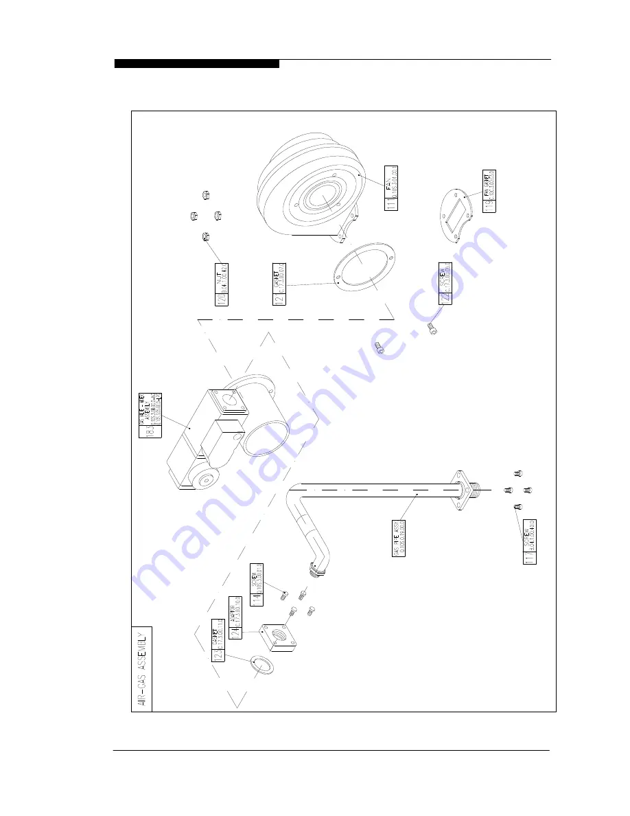
Page 46: ...6 7 3 Air Gas Assembly WD420 3 2007 Chapter 6 Fault Finding The Keston Qudos 28s Qudos 28sP Boilers Installation Servicing Instructions Page 41...
Page 47: ...6 7 4 Casing Assembly WD420 3 2007 Chapter 6 Fault Finding The Keston Qudos 28s Qudos 28sP Boilers Installation Servicing Instructions Page 42...
Page 48: ...tor Kit Q 10S 0 09 00 0 62 Condensate Trap Kit Q 10S 0 16 00 0 58 Flow Return Thermistor Q 10S 2 08 00 0 59 Flue Sensor Q 10S 2 09 00 0 101 Pressure Sensor C 10C 2 17 00 0 57 Flow Thermostat Q 10S 2 0...
Page 49: ...ess replace if necessary e Check for condensate leaks f Check for water soundness g Inspect the flue vent and air intake pipework Joints must be sound and all pipework well bracketed h Check that ther...
Page 50: ...e flue pipe This is situated on the flue spigot out of the cabinet j Carry the full procedure detailed in section 5 7 COMBUSTION TESTING MANDATORY k Replace the combustion test point plug l Recheck th...
Page 51: ...e service cock WARNING Parts of the boiler internal wiring will remain live even after setting the User Controls to Standby Shut off the power supply at the isolating switch before working on the appl...
Page 52: ...ions iv Unscrew the retaining nuts and remove the thermistor v Reassemble Section 8 3 NB When fitting the new thermistor it is an advantage to smear a thin film of heat sink compound between the therm...
Page 53: ...2 item 57 i Isolate the appliance Section 8 1 ii Gain access Section 8 2 iii Remove the push on connector from the sensor taking note of the correct position iv Unscrew the bolts securing the stat Fig...
Page 54: ...ers Fig 6 7 2 2 2 item 103 and 104 fixing the condensate trap to the base of the cabinet iii Disconnect the condense line from the projection of the condensate trap from the base of the cabinet iv Wit...
Page 55: ...he EV bracket Fig 6 7 4 item 39 from the cabinet frame vii Remove the expansion vessel viii Reassemble Section 8 3 NB When reassembling inspect the gasket for damage and replace if necessary WD420 3 2...
Page 56: ...Burner Kit 81 Burner Gasket 72 Ignitor Gasket 53 Ignitor Kit 58 Flow Return Thermistors 59 Flue Thermistor 57 Flow Overheat Thermostat 101 Pressure Sensor WD420 3 2007 Chapter 9 Spare Parts Listings...
Page 57: ...Q28sP Gas Valve Mixer Assem 132 Control Panel 131 Q28s Control PCB Q28sP Con PCB 60 Pump 98 Expansion Vessel WD420 3 2007 Chapter 9 Spare Parts Listings The Keston Qudos 28s Qudos 28sP Boilers Instal...
Page 58: ...59 Flue Thermistor 57 Flow Thermostat 101 Pressure Sensor 111 Fan 183 Gas Valve Mixer Air Gas Assembly NG Q28s 183 Gas Valve Mixer Air Gas Assembly LPG Q28sP 132 Control Panel 131 Control PCB NG Q28s...
Page 59: ...E MEASURE RECORD GAS RATE m3 hr ft3 hr BURNER OPERATING PRESSURE IF APPLICABLE N A mbar CENTRAL HEATING FLOW TEMPERATURE O C CENTRAL HEATING RETURN TEMPERATURE O C FOR COMBINATION BOILERS ONLY HAS A W...
Page 60: ...GNATURE SERVICE 1 DATE ENGINEER NAME COMPANY NAME TEL No CORGI ID CARD SERIAL No COMMENTS SIGNATURE SERVICE 3 DATE ENGINEER NAME COMPANY NAME TEL No CORGI ID CARD SERIAL No COMMENTS SIGNATURE SERVICE...
Page 61: ...conditions Make sure that the exhaust pipe terminates away from windows or vents and is out of reach Make sure that the air inlet and exhaust pipe outlets are at least 200mm apart Check tightness of a...
Page 62: ...00 0 with the LPG gas valve venturi assembly part number Q 10S 3 05 00 0 according to section 8 4 8 v Check the gas rate and combustion MANDATORY Although the gas pressure is preset at the factory it...
Page 63: ...produce a CO2 reading of 10 3 10 7 with a corresponding CO level of 50 150 ppm 4 Press the RESET button once and then press the ENTER button Use the button until the display shows 32 30 for LPG Press...
Page 64: ...0 with the NG gas valve venturi assembly part number Q 10S 3 04 00 0 according to section 8 4 8 v Check the gas rate and combustion MANDATORY Although the gas pressure is preset at the factory it is r...
Page 65: ...t if necessary the adjustment screw pos 4 to produce a CO2 reading of 8 9 9 3 with a corresponding CO level of 50 150 ppm 4 Press the RESET button once and then press the ENTER button Use the button u...
Page 66: ...s Carbon dioxide and carbon monoxide are colorless odorless gases produced by all combustion processes When the Keston condensing boiler is operating properly carbon dioxide CO2 levels will be between...
Page 67: ...will be locked on at Minimum rate If no further buttons are pressed for 10 minutes the boiler will automatically revert to normal operation 5 Measure the CO2 reading in the flue gases The CO2 reading...