


1
1. Digital Meters
JQE models with the suffix DM indicates that the unit has digital meters in place of the analog meters.
(NOTE: analog meters are no longer available.) Voltage meter accuracy is 1%; current meter accuracy is
1.5%. Meter range selector switches are no longer needed with the digital meters and have been
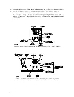
removed on DM models. Refer to Figures 2, 3 and 4 for front panel views of the quarter rack, half rack,
and full rack DM models.
2, PAR. 1-9
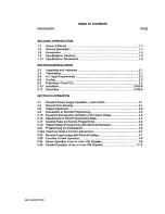
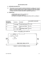
ADD: b) Side Support “L” Bracket P/N 128-1775 mounts to vertical rails to provide additional side support
for rack-mounted models.19.6 in. long x 2.3 in. high x 3.5 in. wide. Two (2) required per unit.
FIGURE 1. SIDE SUPPORT “L” BRACKET P/N 128-1775
3. SECTION III Correction
The instructions throughout Section III are based on a value of the front panel VOLTAGE control (R102)
that requires an
I
b
of 1mA and a corresponding CONTROL RATIO (Kc), also referred to as Programming
Ratio, of 1000 Ohms/Volt.
To allow for the fact that the value of R102 may now be different, use the following procedure to deter-
mine the actual
I
b
and the corresponding CONTROL RATIO (1/
I
b
)
1.
Turn the unit off and disconnect unit from source power.
2.
Remove the link between positions 5 and 6 of TB501 (for JQE quarter rack models: remove link
between positions 6 and 7 of TB1).
3.
Set the Voltage potentiometer on the front panel to full clockwise.
4.
Use a precision digital ohmmeter to measure the resistance between positions 4 and 5 of TB 501
(for JQE quarter rack models: measure resistance between positions 7 and 8 of TB1). This is the
actual resistance of the front panel VOLTAGE control (R102), referred to as
R
VC Internal.
5.
Use the measured value of R102 to calculate I
b
as follows:
I
b
=
(
E
O
+ (
E
O
)
)
/ R
VC Internal
where:
E
O
is the nominal output voltage (Volts).
R
VC Internal
is the value of R102 measured in step 4 (Kilohms).
I
b
is the actual control current.
E
O
functions as voltage headroom to allow full scale from the front panel control.
KEPCO
®
THE POWER SUPPLIER™
OPERATOR MANUAL CORRECTION
JQE MODELS
JQE-r2/030519
KEPCO, INC.
131-38 SANFORD AVENUE
FLUSHING, NY. 11355 U.S.A.
TEL (718) 461-7000
FAX (718) 767-1102
email: [email protected]
World Wide Web: www.kepcopower.com
1
Summary of Contents for JQE 100-1
Page 2: ......
Page 5: ...3 4 Blank FIGURE 4 FRONT PANEL VIEW OF JQE FULL RACK DM DIGITAL METER MODELS ...
Page 6: ......
Page 9: ......
Page 10: ......
Page 11: ......
Page 12: ......
Page 13: ......
Page 14: ......
Page 15: ......
Page 16: ......
Page 17: ......
Page 18: ......
Page 19: ......
Page 20: ......
Page 21: ......
Page 22: ......
Page 23: ......
Page 24: ......
Page 25: ......
Page 26: ......
Page 27: ......
Page 28: ......
Page 29: ......
Page 30: ......
Page 31: ......
Page 32: ......
Page 33: ......
Page 34: ......
Page 35: ......
Page 36: ......