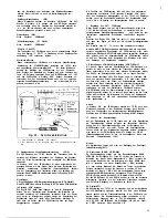
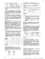
background image

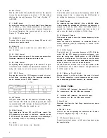
The following optional accessories are available with the

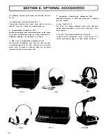
 Light-weight Communication Headphones HS-6

T S - 7 8 0 .

Specifically designed to reduce the weight and to improve

the tone quality.

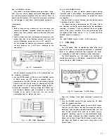
 Communication Externat Speaker SP-7 1

This speaker provides  clear,  natural  tone with the use of a

high-Cut   cone,  best suited for communication use.

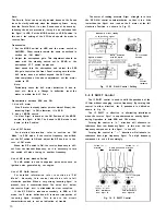
 Communication Headphones HS-4

Specifically designed with consideration given to the shape

of ear pads, materials and weight to  insure  many hours of

fatigueless listening. The impedance is 8  Ohms.

 High  Class Communication Headphones HS-5

The most ideal headphones with “open air” type ear pads

to eliminate pressure to the  head  and ears and to provide

natural  tone. The open air type ear pads  can  be readily

replaced with the pressure type ones.

,

SP-7 1

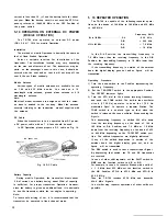
  Ham   Clock  HC-l 0

The HC-10 is a highly advanced world  clock with dual

display  which memorizes 10 world  major  cities and 2  addi-

tional regions.

 De-Luxe Fixed Station  Microphone   MC-60/S8

C o m m u n i c a t i o n   microphone   w i t h   a   p i a n o - t o u c h   P T T

switch  specifically designed for fixed  Station  Operation.

HS-4

HS-5

HC-l 0

MC-60/S8

Summary of Contents for TS-780

Page 1: ......

Page 2: ...efully from cover to cover to insure the maximum Performance and trouble free Operation of your new model TS 780 Save the shipping box and packing in the event your unit needs to be transported for remote Operation maintenance or Service CONTENTS SPECIFICATIONS 2 1 FEATURES 3 2 BEFORE USING 4 3 CONTROLS AND THEIR FUNCTIONS 5 4 PRELIMINARY 9 5 OPERATING INSTRUCTIONS 1 1 6 OPTIONAL ACCESSORIES 2 1 7...

Page 3: ...ance frequency shift Maximum frequency deviation FM f 5 kHz Carrier Suppression Better than 4 0 dB Unwanted Sideband Suppression Better than 40 dB Spurious Radiation Bette r than 60 dB Microphone Impedance 500 600 Q AF Response of Transmitter SSB 400 2600 Hz 9 dB Repeater Frequency Shift 600 kHz or 600 kHz 144 0 146 0 MHz 7 6 MHz or 1 6 MHz 430 0 440 0 MHz RPT Tone Frequency 1 7 50 Hz RECEIVER SEC...

Page 4: ...MHz in 12 bands at 1 MHz intervals 0 Wide band design for both transmitter and receiver that eliminates the need for tuning the RF circuits 0 Panel layout based on human engineering 0 Full variety of indicating functions to check operating conditions OFFSET ON AIR BUSY F LOCK RIT F STEP 0 Amplified type AGC and ALC circuits that maintain receive and transmit Outputs at constant level without disto...

Page 5: ...wlhigh cut typel speaker rated at 4 B ohms is recom mended The Option speaker SP 71 is designed to perfectly match the chara cteristics of the TS 780 Plugging in an externals p e a k e r w i l l automatically disconnect the built in speaker DO not connect the speaker to the PHONES jack as this jack has a level adjusting resistor Extemal speaker SP 71 A Connection of speaker plug When connecting an...

Page 6: ... VOX Switch Standby Switch POWER Switch MIC Connector PHONES Jack MODE Switch PRIO M Switch TIGHT Level F STEP Indicator Tuning Knob FUNCTION Switch MEMORY Selector S S B M I C RIT Indicator RIT Control IF SHIFT Knob S Q U E L C H C o n t r o l SCAN W AF GAIN Control RF GAIN Control F STEP Switch RIT Switch SCAN Switch HOLD M S Switch BAND Switch M Memory Switch F LOCK Switch M R Memory Recall Swi...

Page 7: ...C Connector Connector for microphone up down input and PTT circuit 1 6 PHONES Jack This headphone jack allows use of a set of headphones of 8 l 6 ohms impedance Connect KENWOOD headphones HS 4 5 or 6 available as an optional accessory A stereo headphones may also be connected 17 MODE Switch In FM CH mode the VFO frequency is switched in 20 10 kHz Steps In FM LSB USB or CW mode the VFO frequency is...

Page 8: ...VFO scan circuit The VFO frequency is scanned at the Speed selected by the F STEP switch The switch is also used for re scanning of M S memory scan or for scanning at busy stop 35 HOLD This switch is used to stop scan Operation 3 7 B A N D Switch For selecting the band 144 145 MHz or 430 439 MHz to be operated By pressing the UP switch the frequency is stepped up band by band When the DOWN switch ...

Page 9: ...holder 9 Fuse Holder A 2A fuse When it blows check the Cause and replace with the spare supplied 3 3 INTERNAL VIEW 1 CAR L Carrier Level Control This control adjusts the carrier level in CW mode lt does not function in other modes Use the control within the ALC zone 2 FM MIC Control This control adjusts the sensitivity of the microphone dur ing FM transmission 3 SIDE TONE Control This control adju...

Page 10: ...for the purpose of use budget and installation location In general a beam antenna such as Yagi antenna is suitable for Operation with DX stations or a specific sta tion and a ground plane omnidirectional antenna for Operation with local stations In the case of Yagi anten nas use of a stacked type antenna as shown in Fig 5 will provide excellent directivity and RF gain l Installation Location used ...

Page 11: ...tem which Shows a standing wave ratio of less than 1 5 will insure satisfactory transceive Operation 4 2 COAXIAL CABLE For satisfactory transceive Operation coaxial cable must be used When the transceiver is used for fixed sta tion Service the coaxial cable becomes relatively long so low loss large sized coaxial cable of the shortest possible length should be used as the loss of coaxial cable cann...

Page 12: ...oes not affect the recep display are illuminated to indicate the power is on The digital display indicates 144 000 MHz and VFO A Select your operating frequency band by pressing the DOWN or UP BAND switch The frequency is shifted tion In transmitting Operation however the other Party may be using a fixed channel so it is advisable to set the meter in the Center Position Zero in by adjusting the VF...

Page 13: ...This switch is used to reduce transmit power during Operation with a local Station thus preventing interference to other stations lt is also effective to reduce the power consumption Set the switch to the up Position and the transmit power is reduced to about 1 Watt The transmit power is indicated on the RF meter Since the indication on the RF meter depends on the installation condition of antenna...

Page 14: ...f NB noise blanker Switch The NB switch is used to suppress pulse noise such as ignition noise generated by car engine Use of RF GAIN Control For detailed information refer to section on FM Mode Normally this control should be left in full clockwise position When a very strong incoming Signal is present turn it counterclockwise The noise level below the receive Signal level is attenuated for clear...

Page 15: ...ntrol With the standby switch in the SEND Position adjust the control so that the ALC meter deflects within the ALC zone when the key is pressed down Then release the key Set the standby switch back to REC Position and the meter switch to RF S Position Note If there is a Change in ALC meter deflection reset in the Same manner as in the SSB mode 3 Adjust the side tone The TS 780 has a built in side...

Page 16: ... effective for CW semi break in Operation During CW Operation do notturn the control excessive ly in clockwise direction as it takes a long time until the transceiver returns to receive when the key is released making it impossible to perform smooth semi break in Operation 15 Note If the VOX switch is left ON the TS 780 will momen tarily transmit when the POWER switch is turned on After VOX Operat...

Page 17: ...cy shifts up in 12 5 kHz Steps and in the ON Position in 5 kHz Steps 433 000 433 005 433 0125 433 010 433 0250 433 015 433 0375 433 020 433 9875 433 995 When the MODE switch is changed to or from FM CH Position the operating frequency becomes as shown table 3 Frequency 145 317 7 145 317 6 145 315 0 145 315 displayed 145 312 5 145 315 145 315 0 NOTE 1 NOTE 2 Table 3 Note 1 1 When the F STEP switch ...

Page 18: ...d SCAN W switch 430 431 431 5 432 433 434 436 440 r l il 1 I III 0 5 I 3 5 IO 433 981 5 I __ __ 439 987 __ ____ _ c 5 14 USE OF SCAN SWITCH With the SCAN switch ON the FUNCTION A b flickers to indicate that the frequency is scanned FM CH mode 1 Adjust the squelch sensitivity by the SQL VR and set the Signal level for BUSY stop 2 By setting the SCAN switch to ON the channel is shifted to the next o...

Page 19: ...ven when the F LOCK switch is ON The scan is released when the PRIO M MR or MS switch is set to ON 5 15 USE OF MS MEMORY SCAN SWITCH When the 144 MS or 430 MS switch is set to ON the function CH No flickers to indicate that the memory channels l l 0 ch can be scanned the squelch threshold should be set as in the case of VFO scan With the 144 MS switch ON the memory channel for 144 MHz band can be ...

Page 20: ...pable of the following repeater opera tions on the bands of 144 MHz to 146 MHz and 430 MHz to 440 MHz Frequency Shift 144 to 146 MHz D A 6 0 0 k H z D B 600 kHz 430 to 440 MHz D A 7 6 MHz D B 1 6 MHz In the D A Position the transmitting frequency is 7 6 MHz lower than the receiving frequency In the D B Position the transmitting frequency is 1 6 MHz lower than the receiving frequency If the transmi...

Page 21: ...a 430 MHz band receiver and the VFO B as a 145 MHz band transmitter is not possible because the downlink Signal cannot be monitored In OSCAR Operation it is imperative to use a separate transmitter and receiver so that the downlink Signal can be received as shown in Fig 19 lt is also necessary for you to become acquainted with some special knowledges relative to the Orbit tracking of satellite usa...

Page 22: ... weight to insure many hours of fatigueless listening The impedance is 8 Ohms 0 High Class Communication Headphones HS 5 The most ideal headphones with open air type ear pads to eliminate pressure to the head and ears and to provide natural tone The open air type ear pads can be readily replaced with the pressure type ones SP 7 1 0 Ham Clock HC l 0 The HC 10 is a highly advanced world clock with d...

Page 23: ...ion or insufficient modula FM MIC control in minimum Position Turn FM MIC control clockwise tion VOX not operating 1 VOX switch is OFF 1 Set VOX switch to ON 2 VOX GAIN control in minimum Position 2 Turn VOX GAIN control clockwise Sound Stops when dial is turned quickly in PLL unlock circuit is operating this is normal and is not an indication of trouble F STEP ON Channel scanned first is not clea...

Page 24: ... Bedienungsanleitung für den 70cm 2m FM SSB CW Transceiver TS 780 K E N W O O D TS 780 ...

Page 25: ... 2 m 144 000 146 000 MHz 70 cm 430 000 440 000 MHz SSB A3J CW A1 FM F3 1 5 kHz innerhalb der ersten Betriebsstunde nach 1 Minute Einlaufzeit danach L 500 Hz 30 Minuten Hl 10 W LOW 1 W nur bei FM bei SSB und CW stufenlos einstellbar 10x10 6 5kHz SSB durch Balancemodulator FM Frequenzmodulation durch Reaktanzmodulator 40 dB 40 dB Hl 60 dB LOW 40 dB 500 600 Ohm SSB CW Doppelsuper FM Dreifachsuper 1 Z...

Page 26: ...CH Zuverlässige mechanische und elektrische Funktionen VFO Rasterschritte bei FM Kanalbetrieb FM CH in zwei Stufen einstellbar Schnell FAST mit 12 5 kHz Raster und langsam SLOW mit 5 kHz Raster Drehmoment des VFO Abstimmknopfes durch zuschaltbare Friktionsbremse einstellbar Drucktastengesteuerter Bandschalter mit manuellem Suchlauf vorwärts und rückwärts in 1 MHz lnkrementen innerhalb des gesamten...

Page 27: ...UNG Gasleitungen dürfen auf keinen Fall zur Erdung be nutzt werden Die Erdleitung sollte so kurz wie möglich sein 3 Morsetaste 5 Anschluß des Lautsprechersteckers Den serienmäßig mitgelieferten 3 5 mm Miniatur Klinkenstecker wie gezeigt an das Lautsprecherkabel anlöten dabei aber unbedingt Kurzschlüsse des Nf Ausgangs vermeiden Zur Verhinderung von Hf Einstreuungen und Rückkoppelungen sollte als L...

Page 28: ...ge TX OFFSET Mit diesem Schalter läßt sich bei Duplexbetrieb über Umsetzer die Sendefrequenz gegenüber der Empfangsfrequenz nach oben oder unten verlagern Bei Simplex Betrieb auf Direktkanälen muß der Schalter in Stellung SIMP gebracht werden Der TS 780 arbeitet dann mit gleicher Sende und Empfangsfrequenz Bei Überschrei tung der oberen und unteren Bandgrenzen erfolgt keine Sender Frequenzablage u...

Page 29: ... SSB MIC Mit diesem Regler läßt sich der Mikrofonverstärker bei SSB Sende betrieb auf den richtigen Pegel einstellen Dieser Pegel bestimmt direkt die Sendeleistung während der SSB Aussendung Dazu den Knopf so weit im Uhrzeigersinn drehen daß der Zeiger des Meß instruments 5 nicht über das Ende des ALC Skalenbereichs aus schlägt Durch Reduzierung der Verstärkung ist somit eine stufen lose Regelung ...

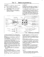
Page 30: ...l CAR L Dieser Regler dient zur Trägerpegel Einstellung bei CW Betrieb In allen anderen Betriebsarten ist er funktionslos Den Regler so einstellen daß der Zeiger des Meßinstruments nicht über das Ende des ALC Skalenbereichs ausschlägt Durch Reduzierung des Trä 0 CAR L Carrier level control g FM MIC control Battery case for backup S TONE Side tone 68 ANTI V ANTI VOX control 6 AUX socket SP jack Pow...

Page 31: ...nd Plane Antenne ausreicht Wegen ihrer ausge zeichneten Richtcharakteristik und ihres hohen Gewinns sind Mehrelement Parabeam und Kreuzyagi Antennen besonders vor teilhaft Fig 5 zeigt die Richtcharakteristik und die Reichweite der verschiedenen Antennentypen in Form eines Strahlungsdiagramms Fig 8 ein Beispiel für eine sehr gute universell verwandbare An tennenanlage o Antennenstandort Um einwandf...

Page 32: ...1 5 f l l H H ntennafeederzi Fig 8 Antennenanschluß 1 Ground Plane Antenne 2 Einspeisungspunkt 3 Das SWR am Einspeisungspunkt darf nicht mehr als 1 5 be tragen Außerdem muß der Einspeisungspunkt völlig wasser dicht sein 4 Coaxkabel 5 Ideale Antenne 6 4 fach gesteckte Yagi Antenne 7 Antennenmast 8 Speiseleitung 9 Antennenbuchse 4 2 Coaxkabel Zur Vermeidung von Störeinstrahlungen und Leistungsverlus...

Page 33: ...r nun in Stellung RF S bringen Da der TS 780 bei FM Empfang breitbandig arbeitet bleiben geringfügige Frequenz schwankungen des RX Signals ohne Auswirkung Falls die Gegen station jedoch auf einer Festfrequenz sendet empfiehlt es sich den Transceiver auf Kanalmitte Nulldurchgang des Signals am VFO Drehknopf abzustimmen l Unter Nullabstimmung versteht man die genaue überein Stimmung der Empfangsfreq...

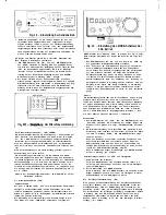
Page 34: ...ei SSB Betrieb MODE Schalter ist in Stellung USB zu bringen wie Fig 12 zeigt Nach erfolgter Einstellung der Regler und Schalter wie folgt fort fahren 1 Den POWER Schalter auf ON und den Regler AF GAIN auf die gewünschte Wiedergabelautstärke einstellen 2 Den Transceiver am VFO Drehknopf langsam so abstimmen bis ein SSB Signal empfangen wird Dazu den VFOzunächst durch Drehen des Knopfes entgegengese...

Page 35: ...m men bei dqen Erreichen ein 800 Hz Schwebungston zu hören ist Die Empfangsfrequenz stimmt dann genau mit der Sende 1Turned In 2 3Turned In direction IF filter passband direction c characteristic i Signal Signal I 4 lnterfering Signal 0 4 lnterfering Signal s r r m wr cmm l 5 Turn In di 6 Turn In di rection t o elimi rection t o elimi nate interference nate Interference from signal B f r o m Signa...

Page 36: ...lautstärke einstellen Das Mikrofon etwa 20 30 cm vor dem Lautsprecher plazieren und den ANTI VOX Regler dann so einstellen daß die vom Laut sprecher abgestrahlten Schallwellen die VOX Steuerung nicht mehr aktivieren Wird der ANTI VOX Regler jedoch zu weit im Uhrzeiger sinn gedreht geht die Ansprechschwelle der VOX Steuerung zurück so daß der Transceiver beim Besprechen des Mikrofons nicht mehr von...

Page 37: ... fühlbar einrastet Beispiele 433 000 433 005 433 0125 433 010 433 0250 433 015 433 0375 433 020 433 9875 433 995 Wird der MODE Schalter auf FM CH eingestellt ändern sich die Betriebsfrequenzen wie in der nachstehenden Tabelle 3 gezeigt Stellung das FM CH b SSB MODE Schalters SSB CW FM bFM CH CW FM Stellung des Schalters F STEP Frequenz Anzeige OFF aus ON ein OFF aus ON fein 145 317 7 145 317 6 145...

Page 38: ... Vorgang wieder holt sich dann laufend mit einem auf 1 MHz beschränkten Such laufbereich 5 14 Der Suchlaufschalter SCAN In Stellung ON des Suchlaufschalters SCAN flackert die FUNC TION Leuchtanzeige A b als Funktionskontrolle des Suchlaufs Betriebsart FM CH FM Kanalbetrieb 1 Den SQUELCH Regler so einsteilen daß der Suchlauf auf be legten Kanälen BUSY eingehalten wird 2 Wird der SCAN Schalter in St...

Page 39: ...nn man die zugehörigen Schalter PRI0 M 9 oder 10 in Stellung ON bringt Werksseitig sind die beiden Kanäle bereits vorprogrammiert und zwar Kanal 9 mit einer Frequenz von 145 000 0 MHz und Ka nal 10 mit einer Frequenz von 433 000 0 MHz wobei beide Kanäle bei Bedarf auch mit anderen Frequenzen belegt werden können Die Frequenzen der beiden Vorzugskanäle werden wie folgt ange zeigt Hinweis 1 Beim Abr...

Page 40: ...ere Umsetzer möglich deren Frequenzablage nicht der üblichen Norm entspricht z B im Ausland 15 20 Funkbetrieb über OSCAR Amateurfunksatelliten Gegenwärtig befinden sich zwei OSCAR Amateurfunksatelliten OSCAR 7 und OSCAR 8 und zwei RADIO Satelliten sowjetischer Funkamateure RS 1 2 auf einer Erdumlaufbahn OSCAR 6 ist nicht mehr funktionstüchtig da seine Batterien erschöpft sind Die genannten Satelli...

Page 41: ...onussystem mit Hochtonbedämpfung verbessert die Verständlichkeit der Empfangssignale vor allem bei SSB Betrieb ganz wesentlich 0 Amateur Kopfhörer HS 4 Preisgünstiger leichter und gequem zu tragender Kopfhörer mit 8 Ohm System Allseitig geschlossene Muscheln mit ring förmigen weichen Kissen Verstellbarer gepolsterter Kopf bügel 0 Amateur Luxuskopfhörer HS 5 Ein Kopfhörer in HiFi Qualität mit hervo...

Page 42: ...Regler FM MIC steht am linken Endan schlag Regler FM MIC im Uhrzeigersinn drehen VOX Steuerung arbeitet nicht 1 VOX Schalter befindet sich in Stellung O F F 2 Regler VOX GAIN steht am linken Endanschlag 1 VOX Schalter in Stellung ON bringen 2 Regler VOX GAIN im Uhrzeigersinn drehen Keine Wiedergabe wenn der VFO Ab stimmknopf in Stellung ON des Schalters F STEP schnell gedreht wird PLL Schaltung is...

Page 43: ...Trio Kenwood Communications GmbH Industriestr 8a 8374Steinbach Taunus West Germany Tel 08171 75035 Telex 410817triod ...

Page 44: ......

Page 45: ......

Page 46: ......

Page 47: ......

Page 48: ......

Page 49: ......

Page 50: ......

Page 51: ......

Page 52: ...it X43 1420 00 Control unit X53 1240 61 PLL unit X50 1770 00 IF unit X48 1350 61 T X unit X56 1420 00 144 MHz final unit ass y X60 1 180 51 Under 430 MHz final unit ass y X60 1 180 00 R F unit X44 1470 00 4 3 0 H E T unit X50 1790 00 27 ...

Reviews: