Kenwood TS-570D, TS-570S Instruction Manual Download Page 2

INFORMATION TO THE DIGITAL DEVICE USER REQUIRED
BY THE FCC

This equipment has been tested and found to comply with the
limits for a Class B digital device, pursuant to Part 15 of the FCC
Rules.  These limits are designed to provide reasonable
protection against harmful interference in a residential
installation.

This equipment generates, uses and can generate radio
frequency energy and, if not installed and used in accordance
with the instructions, may cause harmful interference to radio
communications.  However, there is no guarantee that the
interference will not occur in a particular installation.  If this
equipment does cause harmful interference to radio or television
reception, which can be determined by turning the equipment off
and on, the user is encouraged to try to correct the interference
by one or more of the following measures:

Reorient or relocate the receiving antenna.

Increase the separation between the equipment and
receiver.

Connect the equipment to an outlet on a circuit different from
that to which the receiver is connected.

Consult the dealer for technical assistance.

FCC WARNING

This equipment generates or uses radio frequency energy.
Changes or modifications to this equipment may cause harmful
interference unless the modifications are expressly approved in
the instruction manual.  The user could lose the authority to
operate this equipment if an unauthorized change or modification
is made.

APPLICABLE MODEL

This manual applies to the following model:

TS-570S:  All mode multi-bander

TS-570D:  HF Transceiver

Intelligent Digital Enhanced Communications System

SUPPLIED ACCESSORIES

Carefully unpack the transceiver.  We recommend that
you identify the items listed in the table below.  In
addition, it is safe to keep the box and the packing
material.  You may need to repack the transceiver in
the future.

NOTICE TO THE USER

One or more of the following statements may be
applicable to this equipment.

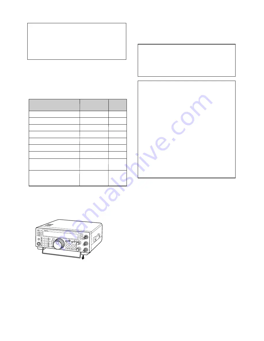
This transceiver is equipped with a bail on the bottom so
that you can angle the transceiver.  Pull the bail forward
to the limit as shown:

Microphone

DC power cable

7-pin DIN plug

13-pin DIN plug

Fuse (25 A)

Fuse (4 A)

Instruction manual

Schematic/block diagrams
(U.S.A. and Canada only)

Warranty card
(U.S.A., Canada, and 
Europe only)

1

1

1

1

1

1

1

1

1

Accessory

Part Number

Quantity

1

1

T91-0352-XX 

E30-3157-XX 

E07-0751-XX 

E07-1351-XX 

F05-2531-XX 

F06-4027-XX 

B62-0898-XX 

For other markets, schematic and block diagrams are 
available as options.

Summary of Contents for TS-570D, TS-570S

Page 1: ...K 0 ENT ENT MIC MIC PWR PWR KEY KEY DELAY DELAY MENU MENU 1MHz 1MHz SPLIT SPLIT M V M V DOWN DOWN UP UP MR MR TF SET TF SET A B A B SCAN SCAN M VFO M VFO M IN M IN M IN M IN FILTER FILTER CW TUNE CW TUNE B C B C N R N R A B A B CLEAR CLEAR RIT RIT XIT XIT RIT XIT RIT XIT IF SHIFT IF SHIFT SQL SQL CH CH 0 10 10 8 A F A F R F R F HIGH HIGH DSP SLOPE DSP SLOPE LOW LOW 0 10 10 8 Intelligent Digital En...

Page 2: ...ates or uses radio frequency energy Changes or modifications to this equipment may cause harmful interference unless the modifications are expressly approved in the instruction manual The user could lose the authority to operate this equipment if an unauthorized change or modification is made APPLICABLE MODEL This manual applies to the following model TS 570S All mode multi bander TS 570D HF Trans...

Page 3: ...f functions such as the Transmit Equalizer Enables Automatic Zero beating for CW operation To pursue user friendliness this transceiver When in Menu mode scrolls messages to tell you what you are selecting Allows you to quickly and easily save the current transceiver settings in Quick memory Is equipped with a large easy to read LCD display WRITING CONVENTIONS FOLLOWED The writing conventions desc...

Page 4: ... SPLIT FREQUENCY OPERATION 23 TF SET TRANSMIT FREQUENCY SET 23 FM REPEATER OPERATION 24 SELECTING SUBTONE FREQUENCY 25 CONTINUOUS OR BURST SUBTONES 25 FM CTCSS OPERATION 25 DIGITAL OPERATION 26 RTTY FREQUENCY SHIFT KEYING 26 AMTOR PACKET PACTOR G TORTM CLOVER 27 SLOW SCAN TV FACSIMILE 28 SATELLITE OPERATION 28 CHAPTER 8 COMMUNICATING AIDS 29 RECEIVING 29 SELECTING YOUR FREQUENCY 29 Direct Frequenc...

Page 5: ...DIX COM CONNECTOR PROTOCOL 70 INDEX 82 ATTENUATOR 37 PREAMPLIFIER 37 DSP TOOLS 37 CHANGING RECEIVE BANDWIDTH 37 SSB FM AM Modes 37 CW FSK Modes 38 BEAT CANCEL 38 NOISE REDUCTION 38 Changing NR1 Performance 38 Setting NR2 Time Constant 38 CHAPTER 10 MEMORY FEATURES 39 MICROPROCESSOR MEMORY BACKUP 39 CONVENTIONAL MEMORY 39 STORING DATA IN MEMORY 39 Simplex Channels 39 Split Frequency Channels 40 MEM...

Page 6: ...terfere with its ventilation Do not place books or other equipment on the transceiver that may impede the free movement of air Allow a minimum of 4 inches 10 cm between the rear of the transceiver and the wall or operating desk shelf 8 Water and Moisture Do not use the transceiver near water or sources of moisture For example avoid use near bathtubs sinks swimming pools and in damp basements and a...

Page 7: ... antenna feed line to ANT 1 If you are using two antennas connect the second antenna to ANT 2 CAUTION TRANSMITTING WITHOUT FIRST CONNECTING AN ANTENNA OR OTHER MATCHED LOAD MAY DAMAGE THE TRANSCEIVER ALWAYS CONNECT THE ANTENNA TO THE TRANSCEIVER BEFORE TRANSMITTING USE A LIGHTNING ARRESTOR TO PREVENT FIRE ELECTRIC SHOCK OR DAMAGE TO THE TRANSCEIVER APPROX LOSS dB PER 30 METERS 100 FEET OF CORRECTL...

Page 8: ...our home from lightning Even in areas where lightning storms are less common there are usually a limited number of storms each year Take the time to study the best way to protect your installation from the effects of lightning by consulting reference material on the subject The installation of a lightning arrestor is a start but there is more that you can do For example terminate your antenna syst...

Page 9: ...H AUDIO OUTPUT AT THIS JACK COULD DAMAGE YOUR HEARING Keys and Keyboards for CW Operation PADDLE and KEY For CW operation using the internal electronic keyer connect a keyer paddle to the PADDLE jack For CW operation without using the internal electronic keyer connect a straight key semi automatic key bug electronic keyer or the CW keyed output from a Multimode Communications Processor MCP to the ...

Page 10: ... to the second function on the button For example repeatedly pressing the LSB USB button switches between LSB and USB modes u Turn the Tuning control to tune in a station If no stations are heard but you have an antenna connected possibly the wrong antenna connector is selected Pressing the ANT button toggles between the Antenna 1 and the Antenna 2 connectors Since you ve now installed the TS 570 ...

Page 11: ...on to activate the Microphone Gain Setting function MIC 50 appears CW Skip this step t Press the SEND button TX appears y Begin speaking into the microphone or sending CW with your key u SSB While speaking into the microphone adjust the MULTI CH control so that the ALC meter reflects according to your voice level CW Skip this step i Press the SEND button again when you want to return to receive mo...

Page 12: ...e 24 or CTCSS function page 25 q q q q q POWER switch Press and hold down briefly to switch ON the transceiver power Press again to switch OFF the power page 13 w w w w w PF button A function can be assigned by the user to this Programmable Function button page 49 The default function is Voice 1 page 55 e e e e e PRE AMP button Press to switch ON or OFF the receive preamplifier page 37 r r r r r A...

Page 13: ...ect your operating mode page 14 LSB USB button Press to select lower sideband or upper sideband mode for voice or digital operation pages 20 27 CW FSK button Press to select CW or frequency shift keying mode pages 21 26 FM AM button Press to select FM or AM mode page 22 4 4 4 4 4 MENU button Press to select or cancel the Menu mode that is used for activating and configuring functions page 16 5 5 5...

Page 14: ...AN button Press to start and stop Scan functions pages 46 47 9 9 9 9 9 M VFO button Press to transfer data from a memory channel to a VFO page 42 0 0 0 0 0 M IN button Writes data into a memory channel page 39 or selects Memory Scroll mode page 41 1 1 1 1 1 Quick Memory buttons Controls the Quick Memory function page 44 M IN button Press to write data into Quick Memory page 44 MR button Press to r...

Page 15: ...the speaker output when no receive signal is present page 14 3 3 3 3 3 MULTI CH control In VFO mode turn to step the operating frequency up or down page 29 In memory channel mode turn to select a memory channel page 40 Also used for selecting Menu numbers when accessing the Menu mode page 16 and as a selector to choose settings for various functions activated by front panel buttons MICROPHONE q q ...

Page 16: ...o used with the Quick Data Transfer function page 60 y y y y y KEY and PADDLE jacks The PADDLE jack mates with a 6 0 mm 1 4 3 conductor plug for connecting a keyer paddle to the internal electronic keyer The KEY jack mates with a 3 5 mm 1 8 2 conductor plug for connecting an external key for CW operation Read Keys and Keyboards for CW Operation page 3 before connecting to these jacks u u u u u ACC...

Page 17: ... strength While transmitting serves as a calibrated power meter plus an ALC meter an SWR meter or a Speech Processor compression meter The Peak Hold function holds each reading for about 2 5 seconds w w w w w Appears while the transceiver is in the transmit mode e e e e e Appears while the squelch is open in the receive mode r r r r r Appears while the internal antenna tuner page 52 or an external...

Page 18: ...Quick Data Transfer page 50 or Computer Control page 51 is being used 1 1 1 1 1 Shows the current operating frequency Also shows Menu selections while in Menu mode 2 2 2 2 2 tA or As appears while VFO A is being selected page 13 A appears while Menu A is being accessed page 16 3 3 3 3 3 tB or Bs appears while VFO B is being selected page 13 B appears while Menu B is being accessed page 16 4 4 4 4 ...

Page 19: ... peak S meter reading of the desired signal Turn the RF control counterclockwise until the S meter reads the peak value that you noted Signals that are weaker than this level will be attenuated Reception of the station will be easier Depending on the type and gain of your antenna and the condition of the band you may prefer leaving the RF control turned counterclockwise by some amount instead of t...

Page 20: ...ully counterclockwise unless operating full carrier modes such as FM or AM SELECTING A FREQUENCY There are two simple methods to select a frequency A Manual Tuning Turn the Tuning control or press Mic UP DWN to select the exact frequency B Direct Frequency Entry Keypad Press ENT then directly enter the desired frequency using the numeric keypad For details refer to Direct Frequency Entry page 29 F...

Page 21: ...W 3 Press PWR again to complete the setting Note The transmit power can be separately selected for the AM mode independent of the other modes MICROPHONE GAIN The microphone gain is finely adjustable in the SSB or AM mode A different level can be selected between when the Speech Processor page 32 is ON and when the Speech Processor is OFF 1 Press MIC The current microphone gain level appears The de...

Page 22: ...signal characteristics DSP settings programmable buttons frequency steps etc Menu B could be configured completely differently By switching from Menu A to Menu B you could instantly change Menu configuration and button assignment to suit your current operating style Or two operators may share a single transceiver By dedicating one Menu per operator each would always enjoy the best configuration No...

Page 23: ......

Page 24: ......

Page 25: ... MCP TNC TX AF output MCP TNC RX Filter bandwidth DISPLAY Brightness DRU 3A DIGITAL RECORDING SYSTEM DRS Playback repeat Playback repeat interval Playback volume DIGITAL SIGNAL PROCESSING NR2 time constant FM Microphone gain Subtone frequency Subtone type 39 11 01 26 27 28 20 22 20 21 36 37 33 34 32 00 23 24 25 12 17 18 19 Function Menu No 03 04 06 05 02 30 29 31 07 08 41 42 43 44 45 46 35 09 10 1...

Page 26: ...is selected 3 Press MIC to activate the Microphone Gain Setting function The current gain level appears 4 Press and hold down Mic PTT or press SEND RX disappears and TX appears Refer to VOX page 31 for information on automatic TX RX switching 5 Speak into the microphone and adjust the MULTI CH control so that the ALC meter reflects according to your voice level Speak in a normal tone and level of ...

Page 27: ...eceiving Neglecting to do this will reduce your chances for being heard by the other station 1 Press CW TUNE to start Auto Zero beat CW TUNE appears Your transmit frequency is automatically changed so that the pitch of the received signal exactly matches the TX sidetone RX pitch frequency that you have set in your transceiver Menu configuration Refer to TX SIDETONE RX PITCH FREQUENCY below for fur...

Page 28: ...n the MULTI CH control to select Wide FM WID or Narrow FM NAR 4 Press FILTER to complete the setting Refer to COMMUNICATING AIDS beginning on page 29 for additional information about useful functions for operating AM TRANSMISSION Each mode used on the HF Amateur bands has its own advantages Although long distance DX contacts may be less common while using AM the superior audio quality characterist...

Page 29: ... CW operation select Semi Break in TF SET TRANSMIT FREQUENCY SET TF SET allows you to temporarily switch your transmit frequency and receive frequency Canceling this function immediately restores the original transmit and receive frequencies By activating TF SET you can listen on your transmit frequency and change it while listening This allows you to check if the newly selected transmit frequency...

Page 30: ...p 2 to another VFO press A B before pressing A B 5 Select the operating frequency The frequency selected on this VFO will be used for receiving 6 Press FM AM to select FM mode 7 Press SPLIT SPLIT appears Pressing A B reverses the receive frequency and the transmit frequency 8 Select the subtone frequency via Menu Nos 18 and 19 See SELECTING SUBTONE FREQUENCY and CONTINUOUS OR BURST SUBTONES for mo...

Page 31: ...e that you select is superimposed on your transmit signal Suppose that only stations A B and C are programmed with the same subtone frequency When A calls the squelch on only B and C opens So you can choose which stations will receive your transmissions 1 Press A B to select VFO A or VFO B tA or tB appears to show which VFO is selected 2 Select the desired subtone frequency via Menu No 18 3 Select...

Page 32: ...n keying down The default is OFF mark 3 Access Menu No 31 and select high tone 2125 Hz or low tone 1275 Hz for mark The high tone default is commonly used nowadays 4 Select the operating frequency 5 Press CW FSK to select FSK FSK appears 6 If necessary to be compatible with the station you want to contact press REV to reverse the transceiver to the upper sideband R appears beside FSK Traditionally...

Page 33: ...ot OFF FSK appears with LSB USB or FM 4 Following the instructions provided with your TNC or MCP enter the calibrate mode so you can generate a mark condition RX disappears and TX appears 5 Use Menu No 33 to select the appropriate AF input level Select a low input level so long as the ALC meter reflects 6 Exit the calibrate mode TX disappears and RX appears 7 Use Menu No 34 to select the appropria...

Page 34: ...ur Speech Processor for best results IARU Region 1 Europe Africa Frequency kHz U S A Canada Frequency kHz 3730 3740 7035 7045 14225 14235 21335 21345 28675 28685 3845 7171 14230 21340 28680 SATELLITE OPERATION Though not as common as VHF UHF satellite operation HF satellite operation is possible depending on which satellites are currently in orbit around the Earth When HF propagation is poor satel...

Page 35: ...ncies stored the receive frequency can be changed by using Direct Frequency Entry within the programmed range Using 1 MHz Steps Pressing UP DOWN on the front panel changes Amateur bands You can also use UP DOWN to change operating frequencies in steps of 1 MHz 1 Press 1MHz 1MHz appears 2 Press UP or DOWN Holding down either button causes the function to repeat 3 To restore the original function pr...

Page 36: ...iver gain and S meter readings to react slowly to large input changes A fast time constant causes the receiver gain and the S meter to react quickly to changes in the input signal A fast AGC setting is particularly useful in the following situations Tuning rapidly Receiving weak signals Receiving high speed CW The default time constant is slow for SSB fast for CW fast for FSK and slow for AM 1 Ass...

Page 37: ...of your voice When using CW mode this level cannot be adjusted 1 Select SSB FM or AM mode 2 Switch the VOX function ON 3 Access Menu No 16 4 While speaking into your microphone using your normal level of voice select different settings default is 4 until the transceiver reliably switches to transmit each time you speak The selectable range is 0 to 9 The final selection should not allow background ...

Page 38: ... using SSB FM or AM mode this leveling action effectively raises the average transmit output power resulting in a more understandable signal The amount of voice compression is fully adjustable You will notice that using the Speech Processor makes it easier to be heard by distant stations 1 Select SSB FM or AM mode 2 Press PROC to switch the Speech Processor ON PROC appears The SWR meter disappears...

Page 39: ...iver is automatically forced to receive mode If you selected transmit mode by pressing SEND transmission will not resume until you select a frequency inside the transmit frequency range and you press SEND again CUSTOMIZING TRANSMIT SIGNAL CHARACTERISTICS The quality of your transmitted signal is important regardless of which on the air activity you pursue However it s easy to be casual and overloo...

Page 40: ...eyboards for CW Operation page 3 for details regarding this connection This built in keyer supports lambic operation CHANGING KEYING SPEED The keying speed of the electronic keyer is fully adjustable Selecting the appropriate speed is important in order to send error free CW that other operators can copy solidly Selecting a speed that is beyond your keying ability will only result in mistakes If y...

Page 41: ...between each series of messages Use Menu No 24 and select the time in the range of 0 to 60 seconds Note This function cannot be used when the Bug Key function is ON Operating the keyer paddle with Menu No 28 OFF cancels message playback Even If message playback does not stop because of your keying start timing you can cancel playback by pressing CLR Storing CW Messages 1 Press CW FSK to select CW ...

Page 42: ...ANGING RECEIVE BANDWIDTH page 37 The default in SSB or AM mode is wide bandwidth In FM mode you cannot change the filter bandwidth Note When you use Menu B make sure to select the appropriate filter bandwidth via Menu No 46 in Menu B 1 Select SSB or AM mode 2 Press FILTER The current filter selection appears 3 Turn the MULTI CH control to select Wide FIL WID or Narrow FIL NAR 4 Press FILTER to com...

Page 43: ...sing DSP technology When in SSB FM or AM mode you can change the filter bandwidth by altering its low cut off frequency and or high cut off frequency For CW and FSK modes you can change the filter bandwidth by directly specifying a bandwidth Changing the filter bandwidth does not affect the current receive frequency You can also monitor signals trimmed off by the above DSP filters Consult PROGRAM ...

Page 44: ... out this does not indicate a malfunction When changing the NR1 level in the menu you will hear sound momentarily caused by an internal operation change this does not indicate a malfunction Setting NR2 Time Constant You can change the correlation time for Noise Reduction 2 When in SSB select the correlation time that allows you to hear signals with more clarity When receiving CW it is best to sele...

Page 45: ...ither method depending on the relationship of the receive and transmit frequencies that you store Simplex channels RX frequency TX frequency Split frequency channels RX frequency TX frequency Memory channels 90 to 99 can also be used as simplex channels Note When RIT or XIT is ON the frequency that includes the RIT or XIT offset will be stored Simplex Channels 1 Press A B to select VFO A or VFO B ...

Page 46: ...hannels until the button is released The memory channels that contain no data are skipped You cannot change memory channels while transmitting 3 To exit Memory Recall mode press M V Note Memory channels can also be changed while using the TF SET function Split Frequency Channels 1 Press A B to select VFO A or VFO B tA or tB appears to show which VFO is selected 2 Select the frequency mode etc to b...

Page 47: ...PLIT to start split frequency operation 6 Press SPLIT again to use the memory channel that you recalled in step 1 7 Press SPLIT once again to quit split frequency operation Memory Scroll 1 Press M IN to enter Memory Scroll mode The memory channel that was last selected appears 2 Turn the MULTI CH control or press Mic UP or DWN to step through the memory channels Entering a 2 digit number such as 0...

Page 48: ...ry Scroll mode press CLR 3 Select the memory channel to which you would like this data copied 4 Press M IN again The tables below illustrate how data is transferred between memory channels Channel 00 89 Channel 00 89 RX frequency TX frequency Mode for RX Mode for TX Subtone frequency Tone ON OFF CTCSS ON OFF Memory Channel Lockout OFF RX frequency TX frequency Mode for RX Mode for TX Subtone frequ...

Page 49: ...99 1 Press M V to enter Memory Recall mode 2 Turn the MULTI CH control or press Mic UP or DWN to select a memory channel 3 Press DOWN to check the start frequency and press UP to check the end frequency Programmable VFO Using the start and end frequencies that you stored in channels 90 to 99 Programmable VFO restricts the frequency range that you can tune with the Tuning control One application of...

Page 50: ...ansceiver provides five Quick memory channels that can store the following data STORING INTO QUICK MEMORY Each time you store a new frequency all previously stored frequencies are bumped to their next respective Quick memory channel When all five memory channels contain frequencies storing one more frequency bumps the contents of memory channel 5 off the stack data lost You can store data in Quick...

Page 51: ...nel you can temporarily change the data without overwriting the contents of the channel You can change the frequency even when you select OFF in Menu No 08 1 Press QUICK MEMO MR 2 Turn the MULTI CH control to select a Quick memory channel 1 to 5 3 Change the frequencies and associated data 4 To store the changed data in Quick memory press QUICK MEMO M IN This action stores the new data in the curr...

Page 52: ...ress SCAN or CLR Note If you have turned the SQL control clockwise far beyond the squelch threshold when in FM mode Scan may fail to stop at a channel in which a signal is present If this happens turn the SQL control slightly counterclockwise If you press SCAN before storing any frequency range then the lower and upper frequency limits of the transceiver are stored in memory channel 90 and Program...

Page 53: ...Starting Memory Scan switches OFF the RIT and XIT functions GROUP SCAN For the purpose of Group Scan the 100 Conventional memory channels are divided into 10 groups with each group containing 10 channels The channels are grouped as follows You can select a maximum of 10 groups and sequentially scan the channels that belong to those groups Group Scan starts with the smallest group number and repeat...

Page 54: ...r ANT 2 ANT 1 or ANT 2 appears to show which antenna is selected The ANT 1 ANT 2 setting will automatically be stored in the current band Each time you select the same band the same setting will automatically be selected The frequency range of each band is shown below Note Connect an external antenna tuner to the ANT 1 connector only After connecting this tuner correctly and selecting ANT 1 the in...

Page 55: ...ted by pressing MIC PWR KEY DELAY or FILTER again When selecting an operating mode a Morse code abbreviation for that mode is heard You can change the volume of the beep output via Menu No 01 DISPLAY DIMMER The Display illumination can be switched between 5 levels via Menu No 00 PROGRAM FUNCTION BUTTON The transceiver allows you to customize the function of the front panel PF button When using the...

Page 56: ...the VFO programmed with a simplex frequency the received data replaces the data on both VFOs On the Slave both RIT and XIT are set to OFF When the Slave receives data using the VFOs programmed with split frequencies the received data replaces the data only on the TX side of the VFO On the Slave XIT is set to OFF but RIT is not changed QUICK DATA TRANSFER This transceiver has the capability to quic...

Page 57: ...nsceiver by computer you must first choose the communication parameters 1 On the computer configure your transceiver control application for 8 data bits and no parity 2 On the transceiver select the appropriate transfer rate and number of stop bits via Menu No 35 The defaults are 9600 bps and 1 stop bit Note To reliably use the 38400 or 57600 bps transfer rates the RS 232C port of the computer mus...

Page 58: ...Menu No 11 ON received signals bypass the internal tuner While using CW Full Break in the internal tuner will be in line for both transmitting and receiving Tuning will automatically turn off after approximately 60 seconds In addition AT will disappear and the error beeps will stop Tuning still may continue when the SWR meter indicates 1 1 This happens because of the tuning algorithm and does not ...

Page 59: ...optional DRU 3A unit allows you to record a voice message on up to 3 channels After recording a message via your transceiver microphone you can then send that message The maximum recording time for each channel is as follows Channel 1 Approx 30 sec Channel 2 Approx 15 sec Channel 3 Approx 15 sec The DRU 3A is useful in many situations DX chasing or contest operation where repeated calls are necess...

Page 60: ...laying back the message in channel 1 To interrupt playback press CLR 5 To play back another message in sequence press the corresponding CH 1 CH 2 or CH 3 while playing back the first message Up to three channels can be queued at the same time 6 If you press SEND or Mic PTT in step 3 press SEND again or release Mic PTT Changing Inter message Interval For repetitive message playback you can change t...

Page 61: ...frequencies are announced beginning with the 10 MHz digit and continuing through to the 10 Hz digit If the memory channel has no data stored open is announced For the MHz decimal point point is announced For the kHz decimal point a short pause 200 ms is made A 200 ms pause also is made between the channel number and the frequency Menu numbers and their settings are announced with a short pause 200...

Page 62: ... function Desktop Microphone MC 90 DSP compatible Desktop Microphone MC 80 Desktop Microphone PC 1A Phone Patch Controller SO 2 Temperature compensated Crystal Oscillator TCXO DRU 3A Digital Recording Unit VS 3 Voice Synthesizer Unit YK 88CN 1 CW Filter 270 Hz IF 232C Interface Unit LF 30A Low pass Filter YK 88C 1 CW Filter 500 Hz MA 5 Mobile 5 band Antenna YK 88SN 1 SSB Filter 1 8 kHz PG 2Z DC Ca...

Page 63: ... bottom case DRU 3A DIGITAL RECORDING UNIT CAUTION SWITCH OFF THE POWER AND UNPLUG THE DC POWER CABLE BEFORE BEGINNING INSTALLATION 1 Remove the bottom case 8 screws 2 Remove the flat cable from the CN15 connector 3 Peel off the paper backing from the cushion installed on the transceiver PC board INSTALLING OPTIONS Cushion CN15 CN17 4 Plug the DRU 3A connector CN901 into the CN17 connector The lar...

Page 64: ... AND UNPLUG THE DC POWER CABLE BEFORE BEGINNING INSTALLATION 1 Remove the 2 screws from the bottom cover of the transceiver 2 Remove the bottom cover 14 INSTALLING OPTIONS 3 Remove the 2 screws from the OPTION FILTER section of the transceiver PC board 4 Align the pins of the transceiver CN8 and CN9 connectors with the two connectors on the filter Take care to properly align the pins 5 While holdi...

Page 65: ...s 8 Insert the SO 2 unit into the specified position on the PC board 9 Turn the PC board over Be careful not to damage the flat cables connected to the PC board and not to drop the SO 2 unit 10 Solder the five pins of the SO 2 unit to the PC board then cut off the SO 2 pins extruding from the PC board 11 Re position the PC board 12 Re install the 13 screws on the PC board 13 Re install the protect...

Page 66: ...nnectors When transferring data to other KENWOOD transceivers use the optional IF 232C interface unit Connect the IF 232C to the ACC 1 connector located on the compatible transceiver 6 pin DIN plugs E07 0654 XX are available as options Contact your dealer or a KENWOOD Service Center CONNECTING PERIPHERAL EQUIPMENT COM connector Personal computer dumb terminal RS 232C serial port TS 570 Straight ca...

Page 67: ...ifiers enter the TX mode when the control terminal is grounded For those amplifiers connect pin 2 of the REMOTE connector to the GND terminal of the amplifier and connect pin 4 of the connector to the control terminal of the amplifier ANTENNA TUNER Use the ANT 1 connector and the AT connector to connect an external antenna tuner If you connect the external tuner to the ANT 2 connector the external...

Page 68: ...ipment must be higher than 1 MΩ If you connect to equipment having lower impedance the S meter will not give accurate readings TNC MCP TS 570 PS 53 13 9 10 11 12 5 6 7 8 1 2 3 4 TNC MCP power supply Personal computer dumb terminal Black Red ACC 2 Connector Rear panel view 1 2 3 4 5 6 7 8 9 10 11 12 13 NC RTK ANO GND PSQ SMET NC GND PKS NC PKD GND SS Pin Name Pin No Not connected RTTY key input AF ...

Page 69: ...rate in accordance with these operating instructions All adjustable trimmers coils and resistors in the transceiver were preset at the factory They should only be readjusted by a qualified technician who is familiar with this transceiver and has the necessary test equipment Attempting service or alignment without factory authorization can void the transceiver warranty When operated properly the tr...

Page 70: ...e transceiver Mode CW AF control Center Menu No 20 CW RX pitch 800 Hz IF SHIFT control Center Receive bandwidth page 38 600 Hz RIT function OFF Break in function VOX OFF 2 Remove the bottom case 8 screws from the transceiver 3 Remove the protective cover installed on the PC board 6 screws 4 Tune in a standard frequency station such as WWV or WWVH at for example 10 000 or 15 000 MHz Adjust the Tuni...

Page 71: ...ing your transceiver is defective Note Due to frequency relationships of some circuits in this transceiver beat tones may be heard on the following frequencies 10 000 MHz 20 000 MHz and 30 000 MHz This is not a fault Placing a powered handy transceiver near this transceiver may cause noise in this transceiver The transceiver will not power up after connecting a 13 8 V DC power supply and pressing ...

Page 72: ...ignals are totally unintelligible Memory Scan will not start scanning Memory Scan will not scan one of the stored channels the desired channel is NOT locked out Program Scan will not start scanning Tuning does not finish successfully The internal tuner is bypassed immediately after tuning is started You cannot transmit even though you press Mic PTT or transmissions result in no contacts 1 Turn the...

Page 73: ... RX levels using Menu Nos 33 and 34 and level controls on your TNC MCP 4 Reorient relocate your antenna or increase your antenna gain 5 Set the TNC MCP TX delay time to more than 300 ms 1 Check the cable and cable connections 2 Use the same parameters in the terminal program and the transceiver Refer to COMMUNICATION PARAMETERS 3 Disconnect the computer from the transceiver and run a utility progr...

Page 74: ... 168 MHz 21 0 21 45 MHz 24 89 24 99 MHz 28 0 29 7 MHz 160 m band 80 m band 40 m band 30 m band 20 m band 17 m band 15 m band 12 m band 10 m band 6 m band Max Min Max Min SSB CW FSK FM AM Transmit max Receive no signal SSB FM AM 1 8 29 7 MHz 50 54 MHz Unwanted sideband suppression modulation frequency 1 0 kHz 40 dB or more 5 kHz or less 2 5 kHz or less 9 99 kHz 600 Ω Wide Narrow 1 2 3 4 5 1 81 MHz ...

Page 75: ... less 0 25 µV or less 0 25 µV or less 1 5 W or more 8 Ω Specifications are subject to change without notice or obligation due to ongoing technological developments SSB CW FSK at 10 dB S N N AM at 10 dB S N N FM at 12 dB SINAD 500 kHz 1 705 MHz 1 705 MHz 24 5 MHz 24 5 MHz 30 MHz 50 MHz 54 MHz 500 kHz 1 705 MHz 1 705 MHz 24 5 MHz 24 5 MHz 30 MHz 50 MHz 54 MHz 28 MHz 30 MHz 50 MHz 54 MHz SSB CW FSK A...

Page 76: ...el data strings The parallel method is faster but more complicated while the serial method is slower and requires less complicated equipment The serial form is therefore a less expensive alternative Serial data transmission uses time division methods over a single line Using a single line also offers the advantage of reducing the number of errors due to line noise Only 3 lines are required theoret...

Page 77: ...the Parameter Table page 73 and the Computer Control Command Tables page 75 to configure the appropriate parameters When configuring parameters be careful not to make the following mistakes correct parameter IS 1000 IS1000 Not enough parameters specified No direction given for the IF shift IS 100 Not enough digits Only three frequency digits given IS 1000 Unnecessary characters between parameters ...

Page 78: ...R VX XT Function Command Antenna Tuner THRU IN LINE and tuning START CANCEL Sets or reads AF gain Auto information Selects antenna connector ANT 1 ANT 2 Sets or reads Beat Cancel Reads busy signals Sets or reads CW Auto Zero beat OFF ON Sets or reads CTCSS tone number 01 39 Sets or reads CTCSS OFF ON MIC DOWN function Sets or reads Menu Sets or reads VFO A frequency Sets or reads VFO B frequency S...

Page 79: ... m o c 2 d n a 1 h t o B 3 3 A N N E T N A R E B M U N 1 1 2 1 T N A 2 T N A t a m r o F o N e m a N o N f o s t i g i D t a m r o F 5 3 U N E M R E B M U N 3 1 5 0 0 0 0 g n i s u d e t n e s e r p e R 6 3 U N E M N O I T C E L E S 4 4 7 e g a p n o e l b a t e e S 8 3 R E T L I F H T D I W 4 g n i s u d e t n e s e r p e R 9 9 9 9 0 0 0 0 9 3 E M I T C G A T N A T S N O C 3 t s a F 2 0 0 w o l S...

Page 80: ...a e p e r k c a b y a l P F F O N O 4 2 l a v r e t n i t a e p e r k c a b y a l P 0 6 0 0 0 0 0 0 c e s 0 6 0 5 2 e m u l o v k c a b y a l P F F O 1 2 3 4 5 6 7 8 9 6 2 g n i t h g i e w o t u A F F O N O 7 2 d e s r e v e r g n i t h g i e w o t u A F F O N O 8 2 k c a b y a l p r e v o y t i r o i r p g n i y e K F F O N O 9 2 t f i h s K S F 0 7 1 0 0 2 5 2 4 0 5 8 0 3 y t i r a l o p K S F ...

Page 81: ...C P1 P2 P3 A C P1 P2 P3 30 30 1 TUNE THRU IN Answer Only TUNE THRU IN TUNE OFF ON u i o 0 w r t y e q 1 2 Parameter Format Parameter function 3 4 5 6 7 8 9 10 11 12 13 14 Input Function Output Set Read Answer 1 2 3 4 5 6 7 8 9 10 11 12 13 14 1 2 3 4 5 6 7 8 9 10 11 12 13 14 AI AUTO INFORMATION Auto information OFF ON A I P1 A I P1 A I P1 32 AI NUMBER Note For other commands controls whether changi...

Page 82: ...6 7 8 9 10 11 12 13 14 DN UP DOWN UP Microphone DOWN UP function DN UP 1 2 Parameter Format Parameter function 3 4 5 6 7 8 9 10 11 12 13 14 Input Function Output Set Read Answer 1 2 3 4 5 6 7 8 9 10 11 12 13 14 1 2 3 4 5 6 7 8 9 10 11 12 13 14 Sets or reads Menu EX EXTENSION MENU P1 35 MENU NUMBER P2 36 MENU SELECTION E X P1 E X P1 E X P2 P2 1 2 Parameter Format Parameter function 3 4 5 6 7 8 9 10...

Page 83: ...MEMORY CHANNEL TX RX MODE FUNCTION SCAN OFF ON SPLIT OFF ON TONE OFF ON TONE NUMBER NOT USED I F I F P1 P7 P4 P3 P5 P8 P9 P10P11P12P13 P14 15 16 17 18 19 20 21 22 23 24 25 26 27 28 29 30 31 32 33 34 35 36 37 38 39 40 41 42 1 2 Parameter Format Parameter function 3 4 5 6 7 8 9 10 11 12 13 14 Input Function Output Set Read Answer 1 2 3 4 5 6 7 8 9 10 11 12 13 14 1 2 3 4 5 6 7 8 9 10 11 12 13 14 DRU ...

Page 84: ... 4 5 6 7 8 9 10 11 12 13 14 Input Function Output Set Read Answer 1 2 3 4 5 6 7 8 9 10 11 12 13 14 1 2 3 4 5 6 7 8 9 10 11 12 13 14 Sets Noise Reduction OFF ON or reads status NR NOISE REDUCTION P1 56 NOISE REDUCTION N R P1 N R P1 N R Parameter Format Parameter function 1 2 3 4 5 6 7 8 9 10 11 12 13 14 Input Function Output Set Read Answer 1 2 3 4 5 6 7 8 9 10 11 12 13 14 1 2 3 4 5 6 7 8 9 10 11 1...

Page 85: ... A P1 R A P1 00 OFF 01 ON Parameter Format Parameter function 1 2 3 4 5 6 7 8 9 10 11 12 13 14 Input Function Output Set Read Answer 1 2 3 4 5 6 7 8 9 10 11 12 13 14 1 2 3 4 5 6 7 8 9 10 11 12 13 14 Lowers raises RIT frequency RD R RIT DOWN UP D U Note This command also affects the XIT frequency same as RIT shift The command functions independently from the RIT XIT control RU Parameter Format Para...

Page 86: ...ter reading SM S METER P1 22 S METER VALUE S M P1 S M Note In transmit mode power meter reading Parameter Format Parameter function 1 2 3 4 5 6 7 8 9 10 11 12 13 14 Input Function Output Set Read Answer 1 2 3 4 5 6 7 8 9 10 11 12 13 14 1 2 3 4 5 6 7 8 9 10 11 12 13 14 Sets or reads squelch level SQ SQUELCH LEVEL P1 46 SQUELCH LEVEL S Q P1 S Q P1 S Q Parameter Format Parameter function 1 2 3 4 5 6 ...

Page 87: ...P1 V D P1 V D Parameter Format Parameter function 1 2 3 4 5 6 7 8 9 10 11 12 13 14 Input Function Output Set Read Answer 1 2 3 4 5 6 7 8 9 10 11 12 13 14 1 2 3 4 5 6 7 8 9 10 11 12 13 14 Sets or reads VOX gain VG VOX GAIN P1 54 VOX GAIN V G P1 V G P1 V G Parameter Format Parameter function 1 2 3 4 5 6 7 8 9 10 11 12 13 14 Input Function Output Set Read Answer 1 2 3 4 5 6 7 8 9 10 11 12 13 14 1 2 3...

Page 88: ...4 LSB see SSB Memory Channels Conventional 39 Erasing 43 Lockout 44 Quick Recalling 45 Quick Storing 44 Quick Transfers to VFO 45 Recalling 40 Resetting 43 Scanning All Channel 47 Scanning Group 47 Scrolling 41 Start End Frequencies 43 Storing Scan Limits 43 Storing Simplex 39 Storing Split Frequency 40 Transfer To Memory 42 Transfer To VFOs 42 Tunable 41 Memory Scan 47 Menu Access 16 Configuratio...

Page 89: ......

Reviews: