


TK-2180
7
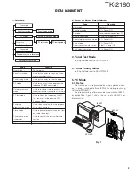
1. Overview
This transceiver is VHF/FM portable transceiver designed
to operate in the frequency range of 136 to 174MHz.
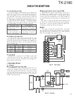
2. Circuit Configuration by Frequency
The receiver is a double-conversion superheterodyne with
a first intermediate frequency (IF) of 59.85MHz and a second
IF of 455kHz. Incoming signals from the antenna are mixed
with the local signal from the PLL to produce the first IF of
59.85MHz.
This is then mixed with the 59.395MHz second local oscil-
lator output to produce the 455kHz second IF. This is de-
tected to give the demodulated signal.
The transmit signal frequency is generated by the PLL
VCO, and modulated by the signal from the microphone. It is
then amplified and sent to the antenna.
3. Receiver System
3-1. RF unit
An incoming RF signal from the antenna terminal is
passed through the antenna switch (D106, D107, D211 and
D213 are off) and then the bandpass filter (L215, L216). The
bandpass filter is adjusted by a variable capacitor. The input
voltage to the variable capacitor is regulated by the voltage
output from the D/A converter (IC605). The signal is ampli-
fied by RF amplifier (Q207), and passed through the band-
pass filter (L211, L214).
The resulting signal is applied to the first mixer (Q206),
where it is mixed with the first local oscillator signal output
from the frequency synthesizer to produce the first IF
(59.85MHz).
3-2. IF unit
The first IF signal is passed through a four-pole monolithic
crystal filter (XF200) to remove a adjacent channel signal. The
filtered first IF signal is amplified by the first IF amplifier
(Q205) and then applied to the lF system IC (IC200). The IF
system IC provides a second mixer, second local oscillator,
limiting amplifier, quadrature detector and RSSI (Received
Signal Strength Indicator). The second mixer mixes the first
IF signal with the 59.395MHz of second local oscillator output
(crystal unit X200) and produces the second IF signal of
455kHz.
The second IF signal is passed through the ceramic filter
(CF201 : Wide, CF200 : Narrow) to more remove the adjacent
channel signal. The filtered second IF signal is amplified by
the limiting amplifier and demodulated by the quadrature de-
tector with ceramic discriminator (CD200). The demodulated
signal is routed to the audio circuit.
ANT
TX/RX : 136~174MHz
ANT
SW
RF
AMP
PA
AMP
TX
AMP
1st MIX
MCF
59.85MHz
CF
455kHz
FM IF
SYSTEM
AF
AMP
SP
59.395MHz
195.85~
233.85MHz
PLL
VCO
MIC
AMP
MIC
136~174MHz
Fig. 1
Frequency configuration
IC200
MIX, DET, IF
SW
SW
Q203
IC606
DMUTE
IC600 (1/2)
AF AMP
2nd local
OSC
X200
VOL
IC605
VC1
VC2
Q618
SSW
SW
ANT
SW
L111,112
L113
L215
L216
BPF
D106,107
D211,213
Q207
RF
AMP
Q206
1st MIX
Q205
IF AMP
ANT
L211
L214
BPF
XF200
MCF
1st Local
OSC (PLL)
CF200
CF201
AQUA-L
IC607
HSDO
SW
Q605
(1/2)
AM2
IC609
AF PA
INT. SP
EXT. SP
Fig. 2
Receiver section
CIRCUIT DESCRIPTION