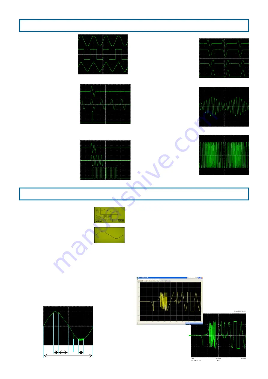
Standard waveform
3 kinds of waveforms, sine,
square, and triangle can be
obtained.
Max. Output is 10Vp-
p(50
Ω
termination), and offset
can be effective until peak volt-
age becomes ±5V
(50
Ω
ter-
mination).
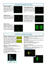
Trigger function
It outputs one cycle for the se-
lected waveform. Manual, inter-
nal signal, or external signal can
be selected as a trigger source.
Burst function
Generation of burst waveform is
possible for all waveforms.
Number of waveforms is from 2
to 99,999.
Photo shows two
numbers of triangle, 5 numbers
of sine, and 10 numbers of
square waveforms from the top.
AM/FM/FSK modulation
Modulation for internal and exter-
nal signals can be made by built-
in AM/FM modulator. FSK modu-
lator to modulate sub carrier with
digital signal is also built-in.
Photo shows AM modulation and
FM modulation from the top.
Function Generator function
Arbitrary waveform function
Setting for arbitrary waveform
Generation of arbitrary waveform with
front panel keys. Operations such as
each data point input, drawing line be-
tween the points, inserting defined
waveform, etc. from front panel keys are
possible. Displaying menu and wave-
form on the 160x80 dot graphic LCD
enables easy data input with confirma-
tion of the process.
①
② ③
⑤
④
[
Example 1 using front panel key
】
Process for generation of the waveform on the photo
is as follows.
1. Download defined waveform.
2. Load enlarged/reducted sine waveforms onto the
plus peak of the initial waveform.
3. Load line between two data points.
4. Add glitch waveform( data point input)
5. Add noise signal onto the minus peak of the ini-
tial waveform.
Generation of arbitrary waveform using applica-
tion software
Using waveform editter Wave-X makes it easy.
It includes pencil function as well as variety of 9kinds of de-
fined waveforms.
Reading waveform memory data from the unit, serving data,
and printing data are possible.
Wave X can be downloaded from our home page.
http://www.kenwoodtmi.co.jp/download/
[
Example 2 Application
】
Generation of waveform inserting Wave X defined waveform
sequentially.
Photo shows Wave X edditer display and actual output
waveform observed by oscilloscope
from the top.
Phase setting function
Starting phase for non-continuous
mode signal can be set.
Setting
range is within ± 360°with 0.1°
resolution.
Photo shows setting
0°,
、
90°, 180°, and 270°from the
top.

