background image

8

Item

Adjustment method/Adjustment value

Conditions

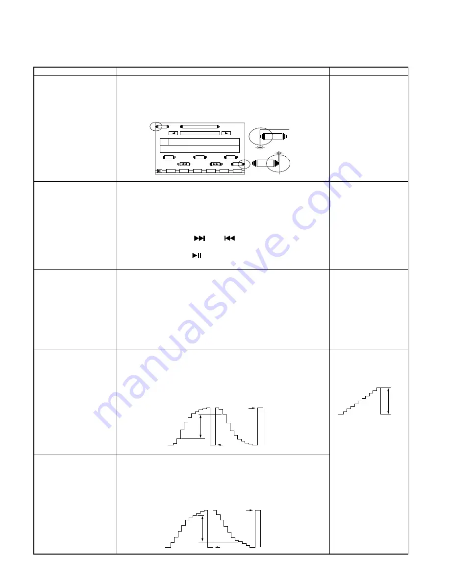
2. Screen display start

1. Display the OSD (RADIO SETTINGS) screen.

• Input signal : OSD

position adjustment

2. Adjust that the 3 vertical lines of A and B part is to be inside the

(RADIO SETTINGS)

VR200

end of the screen by using VR200.

3. Adjust so that the gap of (a) and (b) to be uniform or nothing by

using VR200.

3-1. Video level

1. While pressing and holding VOL DOWN and SOURCE keys, reset

• Must be in test mode.

adjustment mode

the unit.

• Remote controller

2. Enter Video level adjustment mode by pressing DIRECT key of the

(RC-DV100)

remote controller.

• Remote sensor jig

3. The remote controller BAND

DISC and 

M/S keys allow

(Refer to Attention of

adjustment item (CH) selecting.

page 11)

4. The remote controller  

  and  

  keys allow adjustment value

up/down.

5. The remote controller 

 key allows adjustment value fixed (blue

 magenta) and adjustment value released (magenta 

 blue).

3-2. Chroma VCO

1. Select CH : 16 by using the remote controller.

• Input : Video in no

adjustment

2. Connect the check lands (TP35 or TP130, TP36 or TP129) to GND

signal

CH : 16

line.

3. Connect a frequency counter to the check land (TP20 or TP134).
4. Adjust the frequency so that a frequency counter is read 15,734Hz

±

 50Hz by using the remote controller.

5. Fix the adjustment value by using the remote controller.
6. Release the connection between the check lands and GND line,

a frequency counter.

3-3. Bright adjustment

1. Select CH : 6 by using the remote controller.

• Input : Video in

CH : 6

2. Observe the waveform of TP25 on an oscilloscope.

• Input signal : Composite

3. Adjust the amplitude value so that the waveform between the 2nd

SYNC (10 STEP signal)

step from the pedestal and the reversal one is 2.5V

±

 0.1V by using

[NTSC]

the remote controller.

4. Fix the adjustment value by using the remote controller.

• AC range
• Oscilloscope 0.5V/DIV

3-4. Contrast adjustment

1. Select CH : 13 by using the remote controller.

CH : 13

2. Observe the waveform of TP25 on an oscilloscope.
3. Adjust the amplitude value so that the waveform between the 7th

step from the pedestal and the reversal one is 3.0V

±

0.1V by using

the remote controller.

4. Fix the adjustment value by using the remote controller.

LIST

FM

PTY

AM

TP

SETTINGS

RADIO

FM1

98.1

MHz

AUTO1

NO RDS

1

2

3

4

5

6

TP

PTY

A

B

a

b

0.7V

2.5V

SYNC

SYNC

ADJUSTMENT

3.0V

SYNC

SYNC

SVT-M700

Summary of Contents for SVT-M700

Page 1: ... 2002 9 PRINTED IN JAPAN B51 7977 00 N 1864 6 5 INCHES TV MONITOR SVT M700 SERVICE MANUAL GENUINE NUMBER Destination Europe SAAB GENUINE 55 21 372 ...

Page 2: ...tage control of the flyback circuit and the step down type switching regulator for LED9V and BL8 5V power lines IC202 BA7649F Video SW Video in for the adjustment and NAVI signal selector IC301 70F3033AGC1Q6 System MI COM Flash MI COM Mask MI COM IC302 S 80842CNNB Reset IC For Flash MI COM When BU5V line voltage is less than 4 2V IC outputs Lo S 80837CNNB For Mask MI COM When BU5V line voltage is ...

Page 3: ...234 OSD control IC On screen display controller IC501 TC74HC07AFE OSD signal buffer Buffer of R signal G signal B signal I signal and the inverted burst gate pulse signal IC700 BR24C01AF W EEPROM The memory of the touch panel adjustment data and the chroma data IC701 AN2546FH A Video signal processor IC The video signal processing of LCD drive the chroma decoder and γ compensator IC703 NJU7200U30 ...

Page 4: ...utput Not used N C 25 PON O PON output Lo Power ON Hi Power OFF 26 MEC PON O Panel mechanism connection detection input Not used N C 27 MOT SW O Motor applied voltage switching terminal Not used N C 28 30 P111 113 O Not used N C 31 RESET I Reset input terminal Lo Reset 32 XT1 I Sub clock resonator connection terminal Not used pull down to GND lines 33 XT2 Sub clock resonator connection terminal No...

Page 5: ...de position detection input Not used connected to GND lines 75 R SENS I Panel mechanism tilt position detection input Not used connected to GND lines 76 TP XDT I Touch panel X axis voltage input 77 TP YDT I Touch panel Y axis voltage input 78 KEY 1 I Key1 voltage input 0 65V 1 4V NAVI key 2 3V 3 0V DISP key 79 KEY 2 I Key2 voltage input 1 5V 2 2V VOL UP key 80 MEC SW I Panel mechanism connection d...

Page 6: ...ows recall of Video level adjustment mode The remote controller BAND DISC and M S keys al low adjustment item CH selecting The remote controller and keys allow adjust ment value up down The remote controller key allows adjustment value fixed blue magenta and adjustment value released magenta blue Exit by pressing the remote controller DIRECT key again so that all items of Video level adjustment to...

Page 7: ...e as a result of having input incorrect values clear the EEPROM data first and then conduct the adjustment 2 Screen display start 1 With the OSD RADIO SETTINGS screen confirm that the 3 Input signal OSD position confirmation vertical lines of A and B part is to be inside the end of the screen RADIO SETTINGS VR200 2 If they are a little off adjust the 3 vertical lines of A and B part to be inside t...

Page 8: ...9 to GND signal CH 16 line 3 Connect a frequency counter to the check land TP20 or TP134 4 Adjust the frequency so that a frequency counter is read 15 734Hz 50Hz by using the remote controller 5 Fix the adjustment value by using the remote controller 6 Release the connection between the check lands and GND line a frequency counter 3 3 Bright adjustment 1 Select CH 6 by using the remote controller ...

Page 9: ... waveform between the 8th step from the pedestal and the reversal one is 3 5V 0 1V by using the remote controller 4 Fix the adjustment value by using the remote controller 3 7 Y GCA adjustment 1 Select CH 2 by using the remote controller CH 2 2 Observe the waveform of TP25 on an oscilloscope 3 Adjust the amplitude value so that the 9th step from the pedestal is 2 5V 0 1V by using the remote contro...

Page 10: ...l one is 2 7V 0 1V by using the remote controller 4 Fix the adjustment value by using the remote controller 3 11 B Sub bright 1 Select CH 9 by using the remote controller adjustment 2 Observe the waveform of TP26 on an oscilloscope CH 9 3 Adjust the amplitude value so that the waveform between the 2nd step from the pedestal and the reversal one is 2 7V 0 1V by using the remote controller 4 Fix the...

Page 11: ... the remote controller NTSC 4 Fix the adjustment value by using the remote controller AC range Oscilloscope 1 0V DIV 3 15 Exit from Video level 1 Exit from Video level adjustment mode by pressing DIRECT key of adjustment mode the remote controller At this time all adjustment data by using Video level adjustment mode are written to EEPROM 4 Flicker adjustment 1 Input the Composite Gray RASTA NTSC s...

Reviews: