


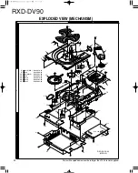

RXD-DV90
4
ADJUSTMENT
L
R
L
L
R
R
VIDEO/AUX
IN
OUT
FRONT SPEAKERS (6
Ω
)
SPEAKERS
S-VIDEO
FM 75
Ω
AM
GND
ANTENNA
SUB
WOOFER
PRE OUT
SURROUND
(8
Ω
)
COMPONENT
VIDEO OUTPUT
VIDEO
OUTPUT
DIGITAL
OUT
OPTICAL
CENTER
(6
Ω
)
+
–
+
–
AC 110-
120V
AC 220-
240V
Cr
Cb
Y
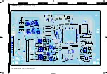
Oscilloscope
FM SG
AUX IN
AUX OUT
AC voltmeter
Frequency counter
AC voltmeter
AG
{
(A)
(B)
Measurement Equipment Connections
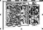
CASSETTE DECK SECTION
INPUT
OUTPUT
CASSETE TAPE
ALIGNMENT
ALIGN FOR
SETTINGS
SETTINGS
DECK SETTINGS
POINT
0dB = 400mV
1. Cassette mechanism section (REC/PB head adjustment)
Power OFF
REC/PB head, Demagnetize the REC/PB head by head
Demagnetization
demagnetization,
erase head.
eraser.Clean the REC/PB head,erase
and cleaning
cleaning play
capstan,pinch head capstan and pinch roller with a
roller
cotton awab immersed in alcohol.
Adjust the output to maximum and
azimuth
MTT-114
Azimuth
adjust the azimuth adjustment screw
REC/PB Head
TCC-153
adjustment
for the Lissajours waveform pattern of
azimuth
10KHz,-10dB
screw
the oscilloscope to become close to a
45' straight line.
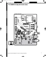
2.PC board adjustment
MTT-111
Adjust the tape speed so that 3kHz is
[1]
Tape speed
TCC-100
AUX OUTPUT
PLAY
VR901
obtained at the center of the tape.
3KHz, -4dB
(Frequency of 3KHZ +/- 40Hz)
[2]
PLAY BACK
MTT-130
AUX OUTPUT
PLAY
–
Playback output to 400mV +/- 50mV
LEVEL
CN902 Pin1 and Pin2(GND)
[3]
REC BIAS
REC/PB
AUX OUTPUT
REC
T901
Ensure that the Frequency Counter
Frequency
TEST TAPE
Adjust T901 to obtain this of 105KHz
AC-224
+/- 5KHz
Record 400Hz and 10.0kHz alternately,
REC/PB
and adjust the bias current adjustment
1.TP1(+) and TP2(GND)
REC BIAS
TEST TAPE
VR903(L)
Adjust VR903(L-CH) to obtain this of 3.5mV
[4]
Current
AC-224
AUX OUTPUT
REC/PLAY
2.TP3(+)
and
TP4(GND)
VR904(R)
Adjust VR904(R-CH) to obtain this of 3.5mV
AUX IN: 50mV
* potentiometer for the playback levels to
400Hz
become the same. (Spec.: +/-5dB)
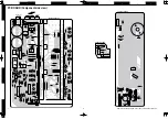
AMPLIFIER SECTION
INPUT
OUTPUT
AMPLIFIER
ALIGNMENT
NO
ITEM
SETTING
SETTING
SETTING
POINT
ALIGN FOR
1.R234 Side Pin1 and Pin3
IDLE
NO SIGNAL
AUX
VR201(L)
Adjust VR201 to obtain this of +8 mV
[1]
CURRENT
VR(Min.)
–
FUNCTION
VR202(R)
1.R301 Side Pin1 and Pin3
Adjust VR202 to obtain this of +8 mV
(Spec.: +8mV +/-3mV)
# Idle Current: 20mA
NO
ITEM
PLAY
[1]
[2]
AUX OUTPUT
(B)
(B)
(B)
(B)
(B)
(A)
–
–