background image

20

MENU MODE

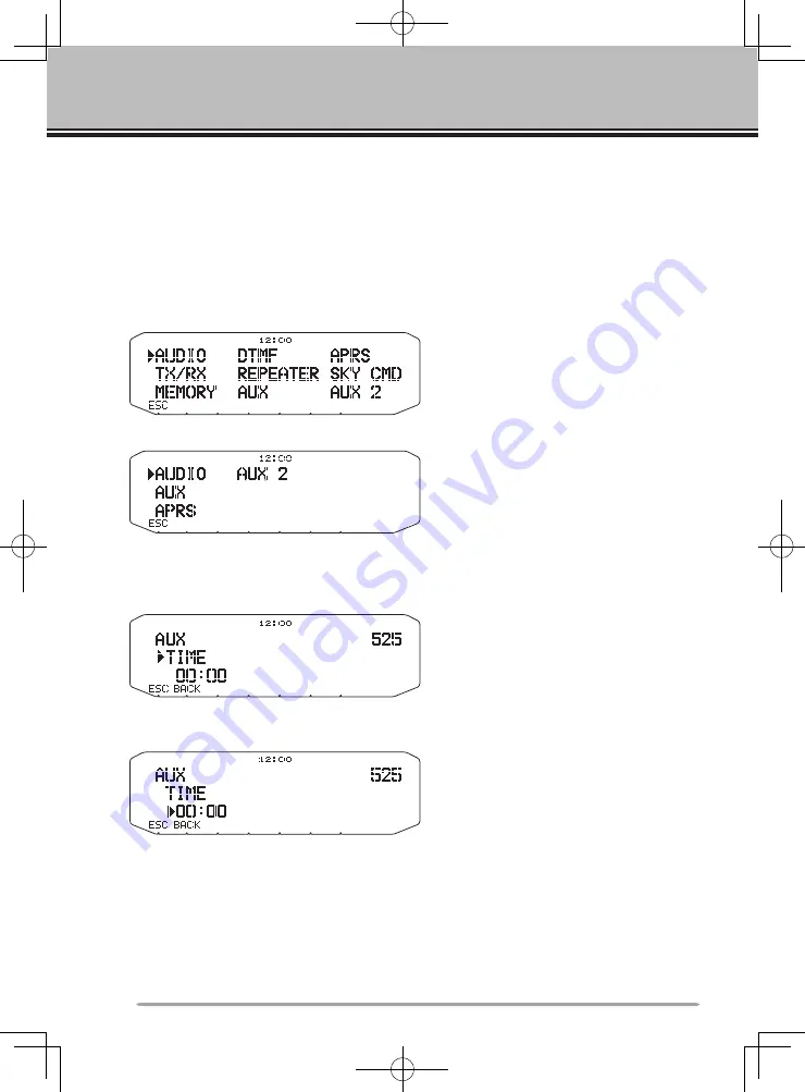
Many functions on this RC-D710 are selected or configured through the Menu 

instead of physical controls.  Once you become familiar with the Menu system, 

you will appreciate the versatility it offers.

MENU AccEss

1

  Press 

[F], Tuning

 control to access the Menu.

•  The setup category name appears on the display.
<RC-D710 + TM-V71>

<RC-D710 + PG-5J>

2

  Rotate the 

Tuning

 control to select your desired setup category.

3

  Press the 

Tuning

 control to set up the current category.

•  The Menu name and number appears on the display.

4

  Rotate the 

Tuning

 control to select your desired Menu.

5

  Press the 

Tuning

 control to set up the current Menu.

6

  Rotate the 

Tuning

 control to select your desired value for the selected Menu.

7

  Press the 

Tuning

 control to set the selected value.

8

  Repeat steps 2 to 7 to set up additional Menus.

•  Press 

[ESC]

 at any time to exit Menu mode.

•  Press 

[BACK]

 at any time to cancel the Menu setup and return to the Menu 

selection.

Summary of Contents for RC-D10

Page 1: ... refer to the PDF file supplied on the CD ROM Seules les fonctions de base sont expliquées dans ce mode d emploi Pour le détail sur les autres opérations reportez vous au fichier PDF à votre disposition sur le CD ROM En este manual de instrucciones solamente se explican las operaciones básicas Si desea obtener una descripción detallada de las operaciones consulte el archivo PDF correspondiente inc...

Page 2: ...CONTROL PANEL RC D710 INSTRUCTION MANUAL ENGLISH ...

Page 3: ...designed to provide reasonable protection against harmful interference in a residential installation This equipment generates uses and can generate radio frequency energy and if not installed and used in accordance with the instructions may cause harmful interference to radio communications However there is no guarantee that the interference will not occur in a particular installation If this equi...

Page 4: ...the RC D710 transceiver power off immediately and contact a Kenwood service station or your dealer Do not use options not specified by Kenwood Writing Conventions Followed in this Manual The writing conventions described below have been followed to simplify instructions and avoid unnecessary repetition Instruction Action Press KEY Momentarily press KEY Press KEY 1s Press and hold KEY for 1 second ...

Page 5: ...ON Panel FRONT RC D710 PG 5J 12 BASIC OPERATIONS RC D710 TM V71 14 Switching THE Power ON OFF 14 Adjusting the Volume 14 ADJUSTING THE SQUELCH 14 Selecting a BAND 15 SELECTING Dual band mode single band MODE 16 SELECTING A frequency band 17 Selecting an Operating mode 18 Transmitting 19 MENU MODE 20 Menu Access 20 Menu Configuration 21 Character Entry 32 MAINTENANCE 34 GENERAL INFORMATION 34 SERVI...

Page 6: ...AN RC D710 TM V71 04 SCAN E pdf CONTINUOUS TONE CODED SQUELCH SYSTEM CTCSS RC D710 TM V71 05 CTCSS E pdf DIGITAL CODED SQUELCH DCS RC D710 TM V71 06 DCS E pdf DUAL TONE MULTI FREQUENCY DTMF RC D710 TM V71 07 DTMF E pdf EchoLink RC D710 TM V71 08 EchoLink E pdf OTHER OPERATIONS 09 OTHER OPERATIONS E pdf PACKET OPERATION 10 PACKET E pdf APRS 11 APRS E pdf RESET 12 RESET E pdf VGS 1 OPTIONAL OPERATIO...

Page 7: ...XX 1 Base stand J09 0409 XX 1 Sheet G11 4438 XX 1 Panel holder J29 0663 XX 1 Cushion G13 2233 XX 1 Panel bracket J29 0707 XX 1 Sheet G11 4228 XX 1 Screw set N99 2055 XX 1 Warranty Card For USA CANADA 1 For Europe 1 Instruction manual English French Spanish Japanese B62 2003 XX 1 Italian German Dutch Chinese traditional B62 2004 XX 1 CD ROM For a detailed explanation on the operation T93 0134 XX 1 ...

Page 8: ...brations may occur After removing the release paper it cannot be reused 3 Attach the panel holder to the panel bracket using the 2 supplied SEMS screws 4 Attach the RC D710 to the panel holder so that it locks in place SEMS screw M4 x 10 mm Panel holder Tapping screw 4 mm x 12 mm Flat washer Adhesive tape Panel bracket n Fixed Station 1 Attach the panel holder to the base stand using the 2 supplie...

Page 9: ...e Installing the Line Filter Install the line filter approximately 3 cm from the connector Approx 3 cm Line filter To PC 9 pin D SUB terminal COM terminal pin NC NC CTS TXD RTS GND RXD NC PG 5G option PG 5G pin configuration cross connection CONNECTION TO TM V71 Connect the RC D710 to the TM V71 using the supplied cable Line filter Panel jack ...

Page 10: ...mini DIN cable DATA terminal Line filter Panel jack Panel jack To 13 8 V DC power supply or 12 V vehicle battery DATA terminal Transceiver No Name I O Function q PKD O TNC data output 2 Vp p 10 kΩ 9600 bps data 40 mVp p 10 kΩ 1200 bps data w GND GND e PKS O Data standby control signal output Open corrector TX L level RX Hi impedance r PR9 I TNC data input 9600 bps 350 mVp p to 600 mVp p 10 kΩ t NC...

Page 11: ... may darken during transmission or the transmit output power may drop excessively Never connect the transceiver to a 24 V battery Note Install the PG 5J Interface Box using the included screw set in a location where it will not interfere with driving n Replacing Fuses PG 5J If the fuse blows determine the cause then correct the problem After the problem is resolved replace the fuse If newly instal...

Page 12: ...hannel Press MR 1s to start Memory scan r Tuning Control Rotate to select an operating frequency or Memory channel change the scan direction etc Press the Tuning control to enter MHz mode while in VFO or Call mode or to toggle the display between the channel name and frequency while in Memory Channel mode Press Tuning control 1s to start MHz scan or Group scan t KEY Press KEY to turn the APRS key ...

Page 13: ...just the speaker volume Press the left BAND SEL to select the A band Press the right BAND SEL to select the B band Press BAND SEL 1s to toggle between single and dual band mode 3 SQL Control Rotate the SQL control to adjust the squelch level Clockwise opens the squelch and counterclockwise tightens the squelch 4 TNC Press TNC to turn built in TNC ON and the APRS or NAVITRA mode ON Each time you pr...

Page 14: ...t F OFF Press F OFF to return Normal mode y T SEL While Tone CTCSS or DCS is ON press T SEL to enter CTCSS or DCS setup mode u SHIFT Press SHIFT to enter Offset Direction selection mode Each time you press SHIFT the offset direction toggles as follows plus direction minus direction 7 6 MHz with TM V71 E E type only OFF i MUTE Press MUTE to turn the Mute function ON or OFF o VISUAL Press VISUAL to ...

Page 15: ...stration mode 4 Press to turn the transceiver power ON and OFF OPERATION Panel REAR LEFT q GPS Connect the GPS receiver or the Weather Station to this jack with using supplied cable with a 2 5 mm 1 10 3 conductor plug w COM This terminal is for connecting to a PC Use a PG 5G option cable when connecting the built in TNC to a computer D SUB terminal e Panel jack Connect the TM V71 or PG 5J to this ...

Page 16: ...type only Appears when the Tone function is ON Appears when the CTCSS function is ON Appears when the DCS function is ON Appears when the Shift function is set to plus Appears when the Shift function is set to minus Appears when the Reverse function is ON Appears when the ASC function is ON Blinks when the ASC function is performing an OK check Appears while in AM mode Appears while in FM mode App...

Page 17: ...power Displays the operating frequency Appears when receiving a busy signal Performs as an S meter when receiving a signal and displays the selected power level while transmitting Appears while transmitting Appears while using the External data band Appears while using the Internal data band Appears when the data terminal is set as 9600 bps Appears when mute function is ON Appears while making a c...

Page 18: ...mode e TNC Each time you press TNC the mode toggles between APRS or NAVITRA mode ON and PACKET mode ON When OPENING TNC appears on the display the mode cannot be changed r PM Press PM to enters the PM Programmable Memory channel selection mode t Press to turn the RC D710 power ON and OFF Note For MSG LIST BCON POS and P MON keys refer to the APRS explanation ...

Page 19: ... OFF Press F OFF to return Normal mode e DX Press DX to turn the DX PacketClusters Monitor ON and OFF r P IN Press P IN to enter PM Channel registration mode t Press to turn the RC D710 power ON and OFF Note For WXi key refer to the APRS explanation n IN FUNCTION MODE ...

Page 20: ...he transceiver OFF Adjusting the Volume Rotate the BAND SEL VOL control of your selected band clockwise to increase the volume and counterclockwise to decrease the volume ADJUSTING THE SQUELCH Rotate the SQL control of your selected band when no signals are present and select the squelch level at which the background noise is just eliminated ...

Page 21: ...nd A and the right BAND SEL control to select band B The icon appears at the top of the band on which you are operating and the icon appears at the top of the band on which you are currently set to transmit Band A left BAND SEL control Band B right BAND SEL control ...

Page 22: ...as the transmit band Band A is the transmit band and band B is the operating band Band A is both the transmit and operating band SELECTING Dual band mode single band MODE You can switch the transceiver between dual band operation and single band operation by pressing BAND SEL 1s of your selected band Dual band mode ...

Page 23: ...display off Menu No 527 SELECTING A frequency band You can change the default frequency bands for bands A and B 1 Select band A or B by pressing the BAND SEL control or PF2 2 Press F BAND SEL of your selected band Each time you press F BAND SEL you cycle to the next frequency band ...

Page 24: ... operating frequency 1 Press VFO to enter VFO mode 2 Rotate the Tuning control to select your desired operating frequency Memory Channel Mode Memory Channel mode allows you to quickly select a frequently used frequency and related data which you have saved in the transceiver memory 1 Press MR to enter Memory Channel mode 2 Rotate the Tuning control to select your desired Memory channel ...

Page 25: ...on the display 3 Press CALL again to return to your previous operating frequency Transmitting 1 Select your desired band and frequency channel 2 Press and hold the microphone PTT switch and speak into the microphone to transmit The icon and the RF power meter appear on the display for the selected transmit band The RF power meter shows the relative transmit output power The icon s appear on the di...

Page 26: ...control to select your desired setup category 3 Press the Tuning control to set up the current category The Menu name and number appears on the display 4 Rotate the Tuning control to select your desired Menu 5 Press the Tuning control to set up the current Menu 6 Rotate the Tuning control to select your desired value for the selected Menu 7 Press the Tuning control to set the selected value 8 Repe...

Page 27: ...ice announcement language ENGLISH JAPANESE ENGLISH 005 1 ANNOUNCE VOLUME Voice announcement volume LEVEL 1 LEVEL 7 LEVEL 5 006 1 ANNOUNCE SPEED Voice announcement speed SPEED 0 SPEED 4 SPEED 1 007 1 PLAYBACK REPEAT Recording playback repeat OFF ON OFF 008 1 PLAYBACK INTERVAL Playback repeat interval time 0 60 s 10 s 009 1 CONTINUOUS RECORDING Continuous recording OFF ON OFF AUDIO RC D710 PG 5J Men...

Page 28: ... OFF 107 MUTE HANGUP TIME Mute hang up time setup OFF 125 250 500 750 1000 ms OFF 108 BEAT SHIFT Beat shift OFF ON OFF 109 TOT Time out timer 3 5 10 min 10 min 110 2 WEATHER ALERT Weather alert OFF ON OFF MEMORY RC D710 TM V71 Menu No Display Description Setting Values Default Setting 200 MEMORY NAME Memory name setup Up to 8 characters 201 RECALL METHOD Memory channel recall method ALL BANDS CURR...

Page 29: ...OCK DTMF key lock OFF ON OFF REPEATER RC D710 TM V71 Menu No Display Description Setting Values Default Setting 400 OFFSET FREQUENCY Offset frequency See explanation 401 3 AUTO REPEATER OFFSET Auto Repeater Offset OFF ON ON 402 1750 TX HOLD Transmission hold when transmitting a 1750 Hz tone OFF ON OFF 403 2 REPEATER MODE Repeater mode CROSS BAND LOCKED TX A BAND LOCKED TX B BAND CROSS BAND 404 2 R...

Page 30: ...pe FRQ BAND E M4 types 508 PANEL PF2 PF2 key programmable function value See explanation CTRL 509 MIC PF1 PF Microphone PF1 key programmable function value See explanation A B 510 MIC PF2 MR Microphone PF2 key programmable function value See explanation MR 511 MIC PF3 VFO Microphone PF3 key programmable function value See explanation VFO 512 MIC PF4 CALL Microphone PF4 key programmable function va...

Page 31: ... type OFF BUSY SQL TX BUSY or TX SQL or TX BUSY or TX 521 AUTO PM STORE Automatic PM entry OFF ON ON 522 2 REMOTE ID Personal Identification Number 000 999 000 523 2 REMOTE ANSWER BACK Answer back OFF ON ON 524 DATE Date See explanation 525 TIME Clock time See explanation 526 TIME ZONE Time zone UTC 14 00 UTC 14 00 UTC 527 DISPLAY PARTITION BAR Display partition bar OFF ON ON 528 COM PORT BAUDRATE...

Page 32: ...ghtness OFF ON OFF 503 BACKLIGHT COLOR Backlight color AMBER GREEN AMBER 504 CONTRAST Display contrast LEVEL 1 LEVEL 16 LEVEL 8 505 DISPLAY REVERSE MODE Display reverse mode POSITIVE NEGATIVE POSITIVE 521 AUTO PM STORE Automatic PM entry OFF ON ON 524 DATE Date See explanation 525 TIME Clock time See explanation 526 TIME ZONE Time zone UTC 14 00 UTC 14 00 UTC 528 COM PORT BAUDRATE COM terminal bau...

Page 33: ...00 bps 1200 bps DCD SENSE DCD sense type D or RxD BAND BOTH BAND IGNORE DCD RC D710 TM V71 D or RxD BAND ON IGNORE DCD RC D710 PG 5J ON TX DELAY TX delay time 100 150 200 300 400 500 750 1000 ms 200 ms 602 GPS PORT BAUD RATE Baud rate speed 2400 4800 9600 bps 4800 bps INPUT GPS data input type OFF GPS WEATHER Da vis WEATHER PeetBros OFF OUTPUT GPS data output type OFF WAYPOINT DGPS OFF 603 WAYPOIN...

Page 34: ... 607 POSITION COMMENT POSITION COMMENT Position comment See explanation Off Duty 608 STATUS TEXT TEXT Status text See explanation TX RATE Status text TX rate OFF 1 1 1 8 1 1 609 PACKET FILTER POSITION LIMIT Position limit See explanation OFF TYPE Packet filter type WHEATHER DIGI MOBILE OBJECT NAVITRA OTHERS Checked all 610 STATION ICON STATION ICON Station icon See explanation W KENWOOD icon 611 B...

Page 35: ...X OFF ON OFF TX INTERVAL Weather TX interval time 5 10 30 min 5 min 616 DIGIPEAT MY CALL DIGIPEAT Digipeat OFF ON OFF 617 UI CHECK TIME UI check time 0 250 sec 28 sec 618 UIDIGI UIDIGI UIDIGI See explanation ALIASES 619 UIFLOOD UIFLOOD UIFLOOD See explanation ALIASES SUBSTITUTION 620 UITRACE UITRACE UITRACE See explanation ALIASES 621 USER PHRASES USER PHRASES User phrases See explanation 622 AUTO...

Page 36: ...play area OFF HALF ENTIRE RC D710 TM V71 ENTIRE OFF ENTIRE RC D710 PG 5J ENTIRE AUTO BRIGHTNESS Auto brightness OFF ON ON CHANGE COLOR Change color OFF ON ON 626 DISPLAY UNIT 1 SPEED DISTANCE Speed distance mi h mile Km h mile Knots nm mi h mile ALTITUDE RAIN Altitude rain feet inch m nm feet inch TEMPERATURE Temperature F C F 627 DISPLAY UNIT 2 POSITION Position format dd mm mm dd mm ss s dd mm m...

Page 37: ...ncy See explanation 88 5Hz 703 2 SKY COMMAND SKY command OFF COMMANDER TRANSPORTER OFF AUX 2 RC D710 TM V71 Menu No Display Description Setting Values Default Setting 998 POWER ON PASSWORD Power on password OFF ON OFF 999 RESET Reset VFO RESET PARTIAL RESET PM RESET FULL RESET VFO RESET AUX 2 RC D710 PG 5J Menu No Display Description Setting Values Default Setting 999 RESET Reset PM RESET FULL RES...

Page 38: ...haracter 3 Press the Tuning control to set the selected character The cursor will move to the next digit You can move the cursor to the left or right by pressing or You can insert one space by pressing SPACE You can insert a character by pressing INS You can delete the selected character by pressing CLR 4 Repeat steps 2 and 3 to enter the remaining characters Press ESC at any time to exit Menu mod...

Page 39: ... T U V 8 3 D E F 3 9 W X Y 9 4 G H I 4 0 space 0 5 J K L 5 Not used 6 M N O 6 For a memory name status text and message Key Character Display with each press of the key 1 q z 1 Q Z 2 a b c 2 A B C 3 d e f 3 D E F 4 g h i 4 G H I 5 j k l 5 J K L 6 m n o 6 M N O 7 p r s 7 P R S 8 t u v 8 T U V 9 w x y 9 W X Y 0 space 0 Not used The microphone A D keys have special functions assigned to them A Functi...

Page 40: ...se do not send subassemblies or printed circuit boards send the complete product A copy of the service report will be returned with the product SERVICE NOTE If you desire to correspond on a technical or operational problem please make your note legible short complete and to the point Help us help you by providing the following Model and serial number of equipment Question or problem you are having...

Page 41: ...s than 450 mA Operating temperature range 20 C 60 C 4 F 140 F Dimensions W x H x D Without projections 155 x 70 x 38 mm 6 10 x 2 76 x 1 50 With projections 156 x 71 x 56 mm 6 14 x 2 80 x 2 21 Weight approx 300 g 10 6 oz To download the MCP 2A software go to http www kenwood com i products info amateur software_download html Note This URL may change without notice ...

Reviews: