


NX-300-K2, NX-300-K4, TK-5320-K2, TK-5320-K4
FCC ID: ALH378501
IC: 282D-378501
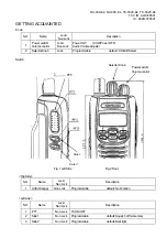
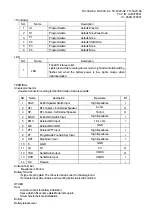
<Front Side>
NO. Name
Description
1
U1
Programmable
default: Zone Up
2
D1
Programmable
default: NoneZone Down
3
P1
Programmable default:
None
4
P2
Programmable
default: CH/GID Up
5
P3
Programmable default:
None
6
P4
Programmable default:
None
LED
NO. Name
Description
1
LED
The LED is three colors.
Lights green while receiving at user mode. Light red while transmitting,
flashes red when the battery power is low .Lights orange when
individual called.
TERMINAL
Universal connector
Universal connector covering for blindfold mode of resin is possible.
NO. Name
Description
Impedance
I/O
1
SSW
Ext/Int Speaker Switch Input
High Impedance
I
2
SP+
BTL for External Speaker
8 ohm
O
3
SP-
BTL Output - for External Speaker
16 ohm
O
4
MSW
Ext/Int MIC Switch Input
High Impedance
I
5
EMC
External MIC Input
1.8 k ohm
I
6
ME
External MIC GND
GND
-
7 PTT
External
PTT
Input
High Impedance
I
8
PF
Programable Function Key Input
High Impedance
I
9 OPT Man
Down
Input
High Impedance
I
10 E
GND
GND
-
11 5U
5V
5V
O
12
TXD
Serial Data Output
CMOS
O
13 RXD
Serial
Data
Input
CMOS
I
14 NC
Reserve
-
--
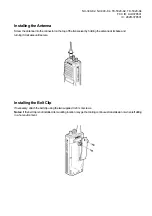
Antenna Terminal
Impedance is 50 ohm
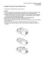
Battery Terminal
It’s type of spring plate. The minus terminal connect to chassis ground
It’s mounted rear side of radio and mounting instruction is slide method.
OTHER
Rear
A rail and a hook for battery installation.
Space which affixes name plate.Model name plate
Screw hole for belt hook installation.
Bottom
Battery release lever


