background image

Installation location and cleaning

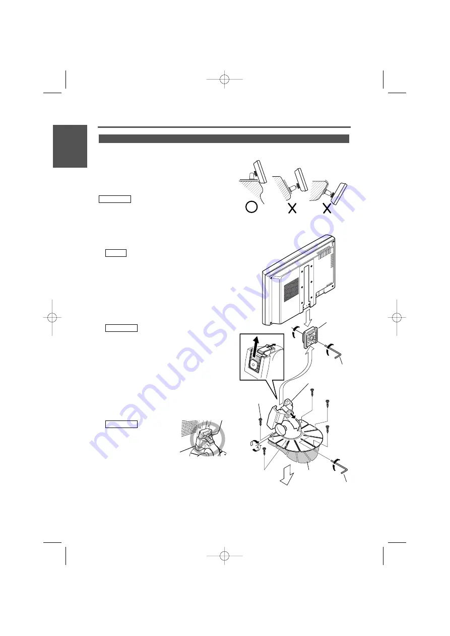
Select for installation a location where the stand can be
placed completely horizontal or where the front edge of
the support (petal-shaped part) can be attached
horizontally as shown in Figure 

A

.

Do not install in locations where the entire support is at a
diagonal such as in Figure 

B

or where the monitor unit is

facing down such as in Figure 

C

.

Thoroughly wipe away and dust or grease from the
installation location using a cloth which has been soaked
in a neutral cleaning agent and wrung out. Attach the
stand after allowing the installation location to dry.

1

Install the shoe on the rear of the TV monitor
temporarily using the supplied hexagon wrench
(Accessary 

C

).

When adjusting the fixing screw of the shoe, use the
hexagon wrench (Accessary 

C

) that came with the

product. Using other hexagon wrenches may damage
the screw.

2

Bend the stand support to conform to the shape of
the installation location.

3

Adjust the shape of the support so that there is no
rattling or gap when the stand is placed on the
support.

4

Peel off the protective strip from the double-sided
tape on the bottom of the stand and securely attach
the stand.

• Do not attach the double-sided tape more than once

or touch the adhesive with your fingers as this will
weaken its adhesive strength.

• If the temperature of the surface of the installation

location is low, warm it up using a heater or other
means before attaching the stand.  Low temperature
may weaken the adhesive strength of the tape.

• The supplied stand is specially intended for this

product. Do not use it with another monitor.

5

Secure the stand using the supplied tapping screw
(Accessory 

D

).

6

After attaching the stand, allow it to sit undisturbed for
24 hours. Take care not to apply any force to the stand
during this time.

7

Insert the shoe of the monitor unit into the bracket
(Accessory 

B

).

Insert the shoe into the
bracket (Accessory 

B

) as far

as it goes.

8

Adjust the height, horizontal and vertical angle of the
monitor unit, and securely tighten the installation
screws using the supplied hexagon wrench (Accessary

C

).

You can also adjust the monitor unit's forward position
by loosening the angle adjustment knobs and
adjusting the angle of the monitor unit's installation
stand.

2

CAUTION

2

CAUTION

NOTE

2

CAUTION

Installation for Monitor Unit

Installation

8 English

English

A

B

C

Accessory 

B

Accessory 

C

Shoe

Accessory 

D

Installation surface

Protective
strip

Tighten

Loosen

Accessory 

C

LZ-651W_ENG r2  03.7.25  9:50 AM  Page 8

Summary of Contents for LZ-651W

Page 1: ...will help you obtain the best performance from your new LZ 651W For your records Record the serial number found on the back of the unit in the spaces designated on the warranty card and in the space provided below Refer to the model and serial numbers whenever you call upon your KENWOOD dealer for information or service on the product Model Serial number LZ 651W_ENG r2 03 7 25 9 50 AM Page 1 ...

Page 2: ...ith the wrong rating may cause your unit to malfunction To prevent short circuits when replacing a fuse first disconnect the wiring harness Do not use any screws except for the ones provided The use of improper screws might result in damage to the main unit You cannot view video pictures whilst the vehicle is moving To enjoy video pictures find a safe place to park and engage the parking brake Kee...

Page 3: ...rarily to the sound used by the navigation system even with the sound through the AV IN being output 9 Screen Mode Select button Each time the button is pressed the screen mode switches as follows FULL ZOOM JUST CINEMA NORMAL NORMAL NAV AV IN OFF Sound of monitoring picture selected by Video Source Select button Sound of navigation system Sound of input video picture from AV IN No sound Set Mode S...

Page 4: ...djusting item BRT Adjusts brightness TINT Adjusts tint Display while displaying the picture from the NTSC signal COL Adjusts color Display while displaying the picture from the PAL signal and the NTSC signal CONT Adjusts contrast BLK Adjusts the black level DIM Adjusts the dimmer when it gets dark 4 Press or button to adjust each item 5 Select RETURN and press to end the Menu mode Also the monitor...

Page 5: ... picture input to AV IN terminal Item Setting VD Switched by the operation of the video source CAM Switched automatically when video signal is input to AV IN terminal OFF It doesn t switch the picture input to AV IN terminal Default setting You cannot set AV IN when NAV is set to AV IN If you set to OFF while the audio source is set to AV IN the audio source would switch to NORMAL BEEP Setup the b...

Page 6: ... screws longer than those supplied may destroy parts inside the unit causing it to smoke Using screws shorter than those supplied may cause the unit to come looks from the installation bracket If you are not going to install the unit using the supplied monitor stand be sure to use a commercially available monitor stand Mounting holes for such a stand are located on the bottom of the monitor unit I...

Page 7: ...with the clamper Accessory A AV cable Commercially available AV input Audio input MONO Visual input Car fuse box Main fuse Battery Ignition cable Red 12V For the sake of safety be sure to connect the parking sensor 2CAUTION When you connect the Mute Cable to the Navigation System the voice of the Navigation guide will interrupt Parking sensor cable Green Ground cable Black To car crassic LZ 651W_E...

Page 8: ...curely attach the stand Do not attach the double sided tape more than once or touch the adhesive with your fingers as this will weaken its adhesive strength If the temperature of the surface of the installation location is low warm it up using a heater or other means before attaching the stand Low temperature may weaken the adhesive strength of the tape The supplied stand is specially intended for...

Page 9: ...stem European Type NTSC PAL Compatible Video input Mini jack x1 Video Input Level 1Vp p 75Ω Audio Input Level 1V 22kΩ RGB Input 13P 0 7Vp p 75Ω General Operating voltage 14 4 V DC 11 16 V Consumed Power 11 W Operational temperature range 10 C to 60 C Storage temperature range 20 C to 85 C Size 180 W x 115 H x 33 D mm 7 1 16 W x 4 1 2 H x 1 5 16 D inches Weight 400g 0 88 LBS Although the effective ...

Page 10: ...mful interference to radio communications if it is not installed and used in accordance with the instructions However there is no guarantee that interference will not occur in a particular installation If this equipment does cause harmful interference to radio or television reception which can be determined by turning the equipment off and on the user is encouraged to try to correct the interferen...

Reviews: