background image

FM•AM TUNER 44W

×

4 AMPLIFIER

HIDEAW

A Y UNIT

KTC-1000R

ANTENNA INPUT

POWER

PREOUT

REAR/NON-F A

D

FR

ONT

SUB WOOFER

REAR SPEAKER

FRONT SPEAKER

DAB

CHANGER

SLAVE UNIT

TV MONITO

R

FM ANTENNA

TO

 MZ-BU

S

TO

 5L I/F

FM•AM TUNER 44W

×

4 AMPLIFIER

HIDEAW

A Y UNIT

KTC-1000R

ANTENNA INPUT

POWER

PREOUT

REAR/NON-F A

D

FR

ONT

SUB WOOFER

REAR SPEAKER

FRONT SPEAKER

DAB

CHANGER

SLAVE UNIT

TV MONITO

R

FM ANTENNA

TO

 MZ-BU

S

TO

 5L I/F

M 4

IN

OUT

NAV

I / F

S

M

NAV.IF

TO MONITOR UNIT

TO MX-BUS

S

M

gS h

24BIT RESOLUTION
D/A CONVERTER

KMD-D400

DASC

11BAND

 SPECTRUM  ANALYZER

500

750

1k

2k

4k

8k

16k

DISP

MENU

]

"N"

O - N

O

N

]

"N"

O - N

Installation

6

English

KTC-1000R

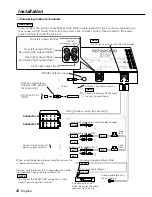
Changer control cable
(Provided with the C907)

Extention cable
(5.5 m)
(Accessory

7

)

Control unit (optional) 

VZ907

M-S switch setting
Set the M-S switch to "S".

2

CAUTION

When the control unit is the KVC-1000

Control unit (optional) 

KVC-1000

Extention cable (5.5 m) (Accessory

7

)

Changer control cable (Black)

KTC-1000R

Changer control cable
(Black)

CD/MD changer (optional)
CD player (optional)

KDC-CPS82, KDC-C712,
KDC-C662, KMD-D400,
KDC-D300, etc.

CD auto changer (optional) 

C907

Changer control cable
(Provided with the C907)

CD auto changer (optional) 

C907

CD/MD changer (optional)
CD player (optional)

KDC-CPS82, KDC-C712, KDC-C662,
KMD-D400, KDC-D300, etc.

When the control unit is the VZ907

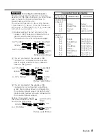
Some model cannot be connected and certain features are unavailable. For details, see
IMPORTANT INFORMATION (see page 2).

NOTE

2

WARNING

2

WARNING

Only connect black cable to
TO 5L interface. Connection
of light-brown connecting
cable (for NAV interface
use) can result in failure.

2

WARNING

DAB tuner (optional)

KTC-959DAB

DAB control cable 
(Provided with the KTC-959DAB)

Summary of Contents for KTC-1000R

Page 1: ...B64 1449 00 E DT 99 6 KTC 1000R HIDEAWAY TUNER AMPLIFIER INSTRUCTION MANUAL ...

Page 2: ...illing a hole in the car to fix the brackets make sure not to damage the fuel tank brake tube wiring harnesses etc on the other side If you experience problems during installation consult your Kenwood dealer Cleaning the Unit If the surface is dirty wipe it clean with a silicon cloth or soft dry cloth with the power off Do not use hard cloths or paint thinner alcohol or other volatile solvents IMP...

Page 3: ...t be linked with the ignition i e it will not turn on and off along with the ignition If you want to link the unit s power with the ignition connect the ignition cable to a power source that can be turned on and off with the ignition key If the fuse blows first make sure that the cables have not caused a short circuit then replace the old fuse with one with the same rating Do not let unconnected c...

Page 4: ...ounded when either the telephone rings or during conversation Power control cable Blue White TEL mute cable Brown To connect the KENWOOD navigation system consult your navigation manual NOTE If you connect the ignition cable red and the battery cable yellow to the car chassis ground you may cause a short circuit that in turn may start a fire Always connect those cables to the power source running ...

Page 5: ...ated 2WARNING BATT ACC BATT ACC BATT ACC Unit Control unit Control unit Control unit Vehicle Ignition cable Red Battery cable Yellow A 7 Pin Red A 4 Pin Yellow BATT ACC BATT ACC BATT ACC Unit Vehicle Ignition cable Red Battery cable Yellow A 7 Pin Red A 4 Pin Yellow Unit Vehicle Ignition cable Red Battery cable Yellow A 4 Pin Yellow 1 Default setting The A 7 pin red of the vehicle s ISO connector ...

Page 6: ...optional VZ907 M S switch setting Set the M S switch to S 2CAUTION When the control unit is the KVC 1000 Control unit optional KVC 1000 Extention cable 5 5 m Accessory7 Changer control cable Black KTC 1000R Changer control cable Black CD MD changer optional CD player optional KDC CPS82 KDC C712 KDC C662 KMD D400 KDC D300 etc CD auto changer optional C907 Changer control cable Provided with the C90...

Page 7: ...ER DAB CHANGER SLAVE UNIT TV MONITOR FM ANTENNA TO MZ BUS TO 5L I F CHANGER 2 TO CHANGER 1 CHANGER 1 TO CONTROLLER TO H U TO SWITCH AUX OFF ON SWITCH PROTOCOL O N IN AUX 1 2 1 2 SWITCH PROTOCOL O N 24BIT RESOLUTION D A CONVERTER KMD D400 DASC R 11BAND SPECTRUM ANALYZER 500 750 1k 2k 4k 8k 16k DISP MENU 24BIT RESOLUTION D A CONVERTER KMD D400 DASC R 11BAND SPECTRUM ANALYZER 500 750 1k 2k 4k 8k 16k ...

Page 8: ...6 mm Accessory3 Installation brackets Accessory1 Velcro strips Accessory4 PROBLEM The power does not turn on No sound can be heard or the volume is low Nothing happens when the buttons are pressed POSSIBLE CAUSE The fuse has blown The Attenuator function is turned on The fader and or balance settings are set all the way to one side The input output cables or wiring harness are connected incorrectl...

Page 9: ...ected to the BUS terminal is set to M Switch the Monitor s M S switch to S The MASTER SW cable of the monitor power supply harness is connected to Do not connect the MASTER SW cable BUS E50 Two or more center units are connected BUS W02 The No switch of the connected disc changers is set to the same number 1 or 2 for both units Set the No switch of one disc changer to 1 and the other unit to 2 to ...

Page 10: ......

Reviews: