background image

17

 EN

ENGLISH

Preparing for surround sound

Speaker settings

To enable you to obtain optimum enjoyment from this model’s listening
modes, make sure to complete the speaker settings (subwoofer, front,
center, and surround speakers) as described below.

1

Turn on the power to this model by pressing POWER ON/
OFF and ON/STANDBY   or POWER   key.

2

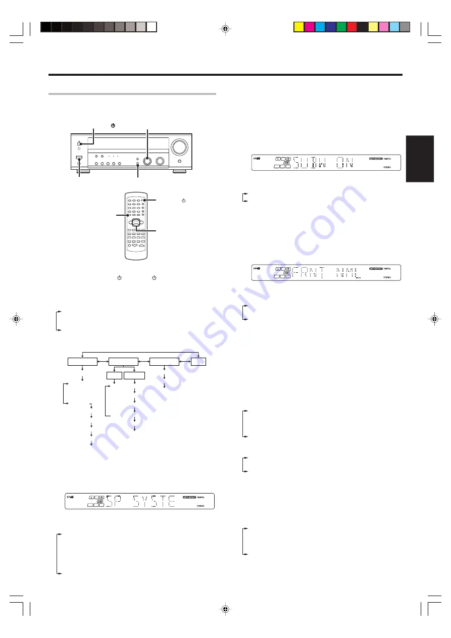
Press the SETUP key to enter the SETUP mode and use the
MULTI CONTROL knob or keys for the following displays.

1

SP SETUP

2

TESTTONE

3

DISTANCE

4

EXIT

The flow of the SETUP is as follows;

SP SETUP

TESTTONE

DISTANCE

EXIT

Front

Center

Surround

SP System

L

C
R

SR

SL

SW

L

C

R

SR

SL

SW

MANUAL

AUTO

Full Range

2Way 2Speaker

2Way 3Speaker

Others

Subwoofer

Front

Center

Surround

Subwoofer Re-mix

3

Select a speaker system.

1

Select SP SETUP and press the SETUP key again so that the
speaker system indication “SP SYSTEM” scrolls across the
display.

2

Use the MULTI CONTROL knob or keys to select the speaker
system setting.

1

FULL RANGE :

For selected KENWOOD speaker – for
example, KS-207HT, KS-207EX, KS-208HT.

2

2WAY 2SPKR :

For selected KENWOOD speaker – for
example, KS-307HT, KS-308HT, KS-308EX.

3

2WAY 3SPKR :

For selected KENWOOD speaker – for
example, KS-707EX.

4

OTHERS

:

For general speakers.

• The selection of FULL RANGE, 2WAY 2SPKR or 2WAY 3SPKR

should only be used with 5 channels speaker system setting.

• When the setting FULL RANGE, 2WAY 2SPKR or 2WAY 3SPKR

is selected, the procedure skips to step 

4

.

3

For general speaker setting, use the MULTI CONTROL knob or
keys to select OTHERS and press the SETUP key again.

• The Subwoofer setting indication “SUBW ON” appears.

4

Use the MULTI CONTROL knob or keys to select the
appropriate Subwoofer setting.

1

SUBW ON :

Subwoofer setting mode to this model is ON.

2

SUBW OFF :

Subwoofer setting mode to this model is OFF.

• The initial setting is “SUBW ON”.
• When the setting “SUBW OFF” is selected, the Front speakers

are automatically set to “FRNT LRG” and the procedure skips to
step 

8

.

Before step 

8

, press the SETUP key to accept the setting.

• When Subwoofer output sound is required, select “FRNT NML”.

5

Press the SETUP key to accept the setting.

• The Front speakers setting indication “FRNT NML” appears.

6

Use the MULTI CONTROL knob or keys to select the
appropriate Front speakers setting.

1


FRNT NML

 (normal)

:

Average size Front speakers are
connected to this model.

2


FRNT LRG

 (large)

:

Large Front speakers are connected
to this model.

• For “FRNT LRG” selection, no sound will be heard from

Subwoofer speaker even when it is set to ON. However, if you
select “SW RE-MIX ON” when Subwoofer is selected, you will
be able to hear sound from the Subwoofer.
When in STEREO mode, the sound goes directly to front speaker.

7

Press the SETUP key to accept the setting.

• The Center speaker setting indication “CNTR NML” appears.

8

Use the MULTI CONTROL knob or keys to select the
appropriate Center speaker setting.

If you have selected “LRG” as the Front speakers setting,

1

CNTR NML

 (normal)

:

An average size Center speaker is
connected to this model.

2

CNTR LRG

 (large)

:

A large Center speaker is connected to
this model.

3

CNTR OFF

:

Center speaker setting mode to this
model is OFF.

If you have selected “NML” as the Front speakers setting,

1

CNTR ON

:

Center speaker setting mode to this
model is ON.

2

CNTR OFF

:

Center speaker setting mode to this
model is OFF.

9

Press the SETUP key again to accept the setting.

•The Surround speaker setting indication “SURR NML” appears.

0

Use the MULTI CONTROL knob or keys to select the
appropriate Surround speaker setting.

If you have selected “LRG” as the Center speaker setting,

1

SURR NML

 (normal)

:

Average size Surround speakers are
connected to this model.

2

SURR LRG

 (large)

:

Large Surround speakers are connected
to this model.

3

SURR OFF

:

Surround speaker setting mode to this
model is OFF.

MULTI CONTROL

SETUP

POWER ON/OFF

SETUP

MULTI 
CONTROL

POWER

ON/STANDBY

Continued to next page

*5446/17-21/EN

04.1.24, 7:10 PM

17

Summary of Contents for KRF-V4080D

Page 1: ...ed to standard remote controls the remote control supplied with this model has several operation modes These modes enable the remote control to control other audio video components In order to effectively use the remote control it is important to read the operating instructions and obtain a proper understanding of the remote control and how to switch its operation modes etc Using the remote contro...

Page 2: ...se a malfunction Be specially careful not to use contact cleaners containing oil for they may deform the plastic component CAUTION RISK OF ELECTRIC SHOCK DO NOT OPEN CAUTION TO REDUCE THE RISK OF ELECTRIC SHOCK DO NOT REMOVE COVER OR BACK NO USER SERVICEABLE PARTS INSIDE REFER SERVICING TO QUALIFIED SERVICE PERSONNEL THE LIGHTNING FLASH WITH ARROWHEAD SYMBOL WITHIN AN EQUILATERAL TRIANGLE IS INTEN...

Page 3: ...ng the system control 16 Preparing for surround sound 17 Speaker settings 17 Normal playback 19 Preparing for playback 19 Listening to a source component 19 Adjusting the sound 20 Recording 21 Recording audio analog sources 21 Recording video 21 Recording audio digital sources 21 Listening to radio broadcasts 22 Tuning non RDS radio stations 22 Using RDS Radio Data System 22 Presetting radio stati...

Page 4: ...revent malfunction Before applying the power 6 m POWER Preparing the remote control Loading the batteries 1 Remove the cover 2 Insert the batteries 3 Close the cover Insert two AA size R6 batteries as indicated by the polarity markings Operating range Approx Remote sensor Infrared ray system 1 2 Unpacking Unpack the unit carefully and make sure that all accessories are present FM indoor antenna 1 ...

Page 5: ...er noise may be output from the analog output It is recommended that you connect the digital output of the player to the digital input of this unit DSP surround modes The DSP Digital Signal Processor used for this model incorporates a variety of high quality adjustable sound fields like ARENA JAZZ CLUB THEATER STADIUM and DISCO It is compatible with almost any kind of program source DVD 6 channel ...

Page 6: ...akers ON OFF ACTIVE EQ key Use to select ACTIVE EQ setting INPUT MODE key 9 Use to switch between full auto digital and analog inputs BAND key Use to select the broadcast band AUTO key Use to change TAPE indication to MD Use to select the auto tuning mode MEMORY key Use to store radio stations in the preset memory SETUP key Use to select the speakers settings etc MUTE key Use to temporarily mute t...

Page 7: ... CD player DISC SKIP key If CD is selected as the input source this key functions as the multi CD player disc skip key 8 BASS BOOST key Use to select the maximum adjustment setting for the low frequency range 9 Input Selector keys DVD 6CH PHONO CD DVD TUNER MD TAPE VIDEO 1 VIDEO 2 Use to select the input sources 4 DVD keys When in DVD player operations these keys function as skip keys 0 DISC SEL k...

Page 8: ... CD player DISC SKIP key If CD is selected as the input source this key functions as the multi CD player disc skip key 8 BASS BOOST key Use to select the maximum adjustment setting for the low frequency range 9 Input Selector keys DVD AUX CD DVD TUNER MD TAPE VIDEO 1 VIDEO 2 Use to select the input sources 4 DVD keys When in DVD player operations these keys function as skip keys 0 DISC SEL key Use...

Page 9: ...n the combination of listening mode and source digital In D MANUAL mode if the audio reproduction stops in the middle due to change in the input signals etc press the LISTEN MODE key If the INPUT MODE key is pressed quickly sound may not be produced Press the INPUT MODE key again Setting up the system Make connections as shown in the following pages When connecting the related system components be...

Page 10: ... AC wall outlet SYSTEM CONTROL jacks Record player Moving coil MC cartridge record player cannot be used directly from this model unit It can only be used when another equalizer amplifier is connected For KRF V4080D only For KRF V5580D only OUT IN Video component IN OUT Cassette deck or MD recorder OUT CD or DVD player 5446 09 16 EN 04 1 24 7 09 PM 10 ...

Page 11: ... video components Video inputs and outputs Yellow RCA pin cords Audio inputs and outputs OUT OUT Monitor TV Video inputs Yellow RCA pin cords VIDEO IN A video component with digital audio outputs should be connected to the VIDEO 2 jacks Video OUT Audio OUT Video OUT Audio OUT DVD player or LD player DVD player or LD player For KRF V5580D 5446 09 16 EN 04 1 24 7 09 PM 11 ...

Page 12: ...AL DIGITAL OUT AUDIO DOLBY DIGITAL RF OUT AUDIO LD player PCM OUT RF digital demodulator Commercially available CD or DVD player OPTICAL DIGITAL OUT AUDIO Optical fiber cable COAXIAL DIGITAL OUT AUDIO Connect the video signal and analog audio signals to the VIDEO 2 jacks See Connecting video components To connect an LD player with a DIGITAL RF OUT connect the LD player to the RF digital demodulato...

Page 13: ... or fire hazard Do not place any object impairing heat radiation onto the top of the unit Leave a space around the unit from the largest outside dimension including projection equal or greater than shown below Top panel 50 cm Side panel 10 cm Back panel 10 cm If you have connected a DVD player to this model with digital connection be sure to read the Input mode settings section carefully 9 SURROUN...

Page 14: ... PRE OUT Setting up the system Connecting the speakers Center Speaker Front Speakers Right Left Subwoofer Powered Subwoofer Right Left Be sure to connect both surround speakers Surround Speakers KRF V4080D To make sure that each speaker has been connected properly pay attention to the test tone from each speaker Refer to 4 Adjust the speaker volume level 5446 09 16 EN 04 1 24 7 09 PM 14 ...

Page 15: ...oustic imaging Be sure to connect the speakers correctly Connecting the antennas AM loop antenna The supplied loop antenna is for use indoors Place it as far as possible from this model TV set speaker cords and power cord and adjust the direction for best reception FM indoor antenna The supplied indoor antenna is for temporary use only For stable signal reception we recommend using an outdoor ante...

Page 16: ...ol operations the components must be connected to the correct jacks To use a CD player it must be connected to the CD jacks To use a cassette deck or MD recorder it must be connected to the MD TAPE jacks When using more than one CD player etc only the one connected to the specified jacks may be connected for system control Some CD players and cassette decks are not compatible with the SL16 system ...

Page 17: ...FF is selected the Front speakers are automatically set to FRNT LRG and the procedure skips to step 8 Before step 8 press the SETUP key to accept the setting When Subwoofer output sound is required select FRNT NML 5 Press the SETUP key to accept the setting The Front speakers setting indication FRNT NML appears 6 Use the MULTI CONTROL knob or keys to select the appropriate Front speakers setting 1...

Page 18: ... be skipped 3 Press the SETUP key The test tone is turned off This model enters the mode for inputting the distance to the speakers 4 For MANUAL selection press the SETUP key each time to select the speaker channel 5Input the distance to the speakers 1 Select the DISTANCE from the set up displays and press the SETUP key again 2 Measure the distance from the listening position to each of the speake...

Page 19: ... you have selected a component connected to the CD DVD VIDEO2 DVD KRF V5580D only or DVD 6CH KRF V4080D only jacks make sure that the input mode setting is correct for the type of audio signal to be used 9 Selecting MD TAPE Select the source name corresponding to the component connected to the MD TAPE jacks The initial factory setting is TAPE To change the source to MD follow the steps below 1 Use...

Page 20: ...OUDNESS setting ON To cancel Press the LOUDNESS key again so that the LOUDNESS indicator goes off Muting the sound The MUTE key lets you mute the sound of the speakers Press the MUTE key To cancel Press the MUTE key again so that the MUTE indicator goes off MUTE ON can also be deactivated by turning the volume control knob ACTIVE EQ mode You can enjoy a more impressive sound effect when ACTIVE EQ ...

Page 21: ...MMER 1 Use the INPUT SELECTOR knob to select the source CD DVD DVD KRF V5580D only or DVD 6CH KRF V4080D only or VIDEO2 you want to record 2 Set the MD or TAPE recorder to record 3 Press and hold the DIMMER key for more than 2 seconds to select the A REC or M REC mode during digital input 1 Rec mode off The digital input record mode is switched off 2 A REC mode The digital input signals DTS Dolby ...

Page 22: ... operation by referring to the description in Presetting RDS stations RDS AUTO MEMORY Listening to radio broadcasts This model can store up to 40 stations in the memory and recall them by one touch operation Radio stations can be classified into RDS Radio Data System stations and other stations To listen to or store RDS stations in the preset memory see Using RDS Radio Data System Tuning non RDS r...

Page 23: ...tions TUNER Numeric keys 1Press the TUNER key to select tuner as the source Listening to radio broadcasts 2Enter the number of the preset station you want to receive up to 40 Press the numeric keys in the following order For 15 press 0 5 For 20 press 0 0 If you make a mistake entering a two digit number press the 10 key repeatedly to return to the original display and start again Receiving preset ...

Page 24: ...isplay Displays the frequency of the current station Presetting RDS stations RDS AUTO MEMORY This function automatically stores up to 40 RDS stations in the preset memory In order to use the PTY function the RDS stations must be stored in the preset memory using the RDS AUTO MEMORY function INPUT SELECTOR BAND AUTO MEMORY 1Use the INPUT SELECTOR knob to select the tuner 2Use the BAND key to set th...

Page 25: ...Y Preparations Execute the RDS auto memory procedure Set the broadcast band to FM Tune to an RDS station 1Press the PTY key to activate the PTY search mode When an RDS broadcast is received the program type is shown on the display If no PTY data is available or if the station is not an RDS station NONE is displayed 2While the PTY indicator is lit use the MULTI CONTROL or TUNING 1 keys to select th...

Page 26: ...ormance in the other surround modes Dolby Digital has a 1 or LFE channel The indication LFE appears in the display when a signal is being input for this channel Dolby PRO LOGIC II Dolby Pro Logic II was designed specifically to provide a new sense of spatiality directionality and articulation of sounds from Dolby Surround encoded sources such as video and Laserdisc software marked This is achieved...

Page 27: ...ct of decaying elements of sound echoing in various places The DSP modes produce the feeling of presence by using the DSP to create reverberation without spoiling the sound quality of the original signal DTS mode The DTS multi channel audio format is available on CD LD and DVD software DTS is a strictly digital format and cannot be decoded inside most CD LD or DVD players For this reason if you at...

Page 28: ...icator lights up 3 PL II MUSIC PRO LOGIC II surround MUSIC mode The PRO LOGIC indicator lights up 4 PRO LOGIC PRO LOGIC II surround PRO LOGIC mode The PRO LOGIC indicator lights up 5 STEREO Normal stereo playback The STEREO indicator lights up When you select DOLBY DIGITAL DOLBY DIGITAL will scroll from right to left When the DTS signal is input The DTS LED indicator lights up 1 DTS DTS surround 2...

Page 29: ...peaker level adjustment 2 SR Surround Right speaker level adjustment 3 SL Surround Left speaker level adjustment 4 SW Subwoofer level adjustment 5 INPUT input level adjustment analog mode only 6 NIGHT midnight mode ON OFF Dolby Digital mode only 7 PANORAMA panorama mode ON OFF 8 DIMENSION dimension adjustment 9 CENTER WIDTH center width adjustment The adjustment is only temporary for the current i...

Page 30: ...o music through center image from only center speaker or left and right speakers or various combinations adjustments 1 Press the SOUND key repeatedly until CENTER WIDTH appears on the display The CENTER WIDTH indication scrolls across the display When the center speaker is switched OFF this mode will not be effective 2 Use the MULTI CONTROL knob or keys to adjust the left center right output Cente...

Page 31: ...w to operate the DVD player with the remote control 1 Pressing the DVD Power key for more than 2 seconds turns the DVD player on or off 2 To carry out the functions of the DVD player first press the DVD Power key then press each key for each operation as explained in the DVD operation pages in the operating instructions In this case the DVD operation mode is retained for 15 seconds after pressing ...

Page 32: ...DE DVD DISC SEL ACTIVE EQ LOUDNESS TOP MENU RDS DISPLAY TONE Numeric keys Select tracks 6 Play Pause Skip up DISC SKIP 1 Search Search 4 Skip down 7 Stop For RC R0627 only DVD 6CH For RC R0627 only PHONO DOWN PAGE UP PTY MD recorder operations keys 1 DISC SKIP BASS BOOST AUTO AUX CD DVD DVD TUNER MD TAPE VIDEO1 VIDEO2 2 3 POWER DVD POWER RECEIVER MENU P CALL TUNING MUTE VOLUME A B 100 ENTER BAND P...

Page 33: ... is not output from the surround speakers and or the center speaker or their sound is very soft A humming noise is generated when the PHONO input selector is selected For KRF V4080D only When playing a Dolby Digital source signal using a DVD player the sound is cut off soon after it starts No sound is produced during playback from a DVD player A video source cannot be recorded normally In case of ...

Page 34: ...properly No tape or CD is placed in the source component An attempt is made to play a tape which is being recorded in the cassette deck Remedy Press the source select keys or DVD POWER keys to select the appropriate operation mode Replace with new batteries Operate the remote control unit within the controllable range Connect properly referring to Setting up the system Place the tape or CD in the ...

Page 35: ...kHz Loudness control VOLUME at 30dB level 8 dB at 100 Hz DIGITAL AUDIO section Sampling frequency 32 kHz 44 1 kHz 48 kHz 96kHz Input level impedance wave length Optical 15 dBm 21 dBm 660 nm 30nm Coaxial 0 5 Vp p 75 Ω VIDEO section VIDEO inputs outputs VIDEO composite 1 Vp p 75 Ω FM tuner section Tuning frequency range 87 5 MHz 108 0 MHz Usable sensitivity DIN at 75 Ω MONO 1 3 µV 13 2 dBf 40 kHz DE...

Page 36: ...n the spaces designated on the warranty card and in the space provided below Refer to the model and serial numbers whenever you call upon your dealer for information or service on this product Model_____________________ Serial Number_____________________ 5446 31 36 EN 04 1 24 7 26 PM 36 ...

Reviews: