background image

30

CONNECTING THE FEEDER CABLE

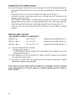
To connect the feeder cable to the hob it is necessary to carry out the following operations:
• 

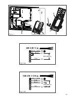
Unhook the terminal board cover “

A

” by inserting a screwdriver into the two hooks “

B

” 

(fig. 5.1).

• 

Unscrew the screw “

C

” and open completely the cable clamp “

D

” (fig. 5.1).

• 

Connect the phase, neutral and earth wires to terminal board “

E

” according to the 

diagram in fig. 5.2a or 5.2b.


The U bolt “

F

” shall be used or not depending on the type of connection; it is supplied 

already fitted to the terminals or inside the terminal board, close to the cable clamp “

D

” .

• 

Strain the feeder cable and block it with cable clamp “

D

” (by screwing screw “

C

”) .

• 

Close the cover “

A

” of the terminal board “

E

” (check the two hooks “

B

” are correctly 

hooked) .

FEEDER CABLE SECTION

“Type H05RR-F, H05VV-F or H05V2V2-F”

220-240 V ac  


3 x 2,5 mm

2

 (*)   

induction power=6800 watt max (***)

380-415 V 2N ac   

4 x 1,5 mm

2

 (*)   

induction power=6800 watt max (***)

380-415 V 3N ac   

5 x 1,5 mm

2

 (*)  (**) 

induction power=6800 watt max (***)

(*)  Connection with wall box connection


– Diversity factor applied


– A diversity factor may be applied to the total loading of the appliance only by a 

suitably qualified person

(**) 

Same diagram as per fig. 5.2b (380-415 V 2N ac) but with one phase not connected 

on the electrical mains supply

(***) The maximum power limit of the appliance can be reduced as indicated in chapter 

“MAXIMUM POWER MANAGEMENT”

If the supply cord (not supplied with the appliance) is damaged, it must be replaced 

by the manufacturer or its service agent or a similarly qualified person in order to 

avoid a hazard.

Summary of Contents for KH600B-IND

Page 1: ...TOUCH CONTROL INDUCTION COOKING HOBS model KH600B IND Instructions for use Installation advice Before operating this cooker please read these instructions carefully 0 9 P 1 2 3 4 5 6 7 8 ...

Page 2: ...duction 3 Important Safety Precautions and Recommendations 4 7 Features and Tecnical Data 8 Use of Induction Hob 9 24 Cleaning and Maintenance 25 Advice For The Installer 26 Installation 27 28 Electrical section 29 31 Guarantee 32 ...

Page 3: ...roper and dangerous This appliance has been designed constructed and marketed in compliance with Safety requirements of the Low voltage Directive 2014 35 EU Safety requirements of the EMC Directive 2014 30 EU Requirements of EU Directive 93 68 EEC Requirements of EU Directive 2011 65 EU Dear Customer Thank you for purchasing a Kenwood Induction Hob The safety precautions and recommendations in the...

Page 4: ...people with sensitive skin may have a more pronounced temperature perception with some components although these parts are within the limits allowed by the norms The complete safety of the appliance also depends on the correct use we therefore recommend to always pay a extreme attention while using the product especially in the presence of children After having unpacked the appliance check to ensu...

Page 5: ... and environmental protection regulations ensuring in particular that all potentially hazardous parts be made harmless especially in relation to children who could play with unused appliances The various components of the appliance are recyclable Dispose of them in accordance with the regulations in force in your country If the appliance is to be scrapped remove the power cord After use ensure tha...

Page 6: ...electric shock and call Customer Service WARNING When correctly installed your product meets all safety requirements laid down for this type of product category However special care should be taken around the underneath of the appliance as this area is not designed or intended to be touched and may contain sharp or rough edges that may cause injury CAUTION The cooking process has to be supervised ...

Page 7: ...induction cooking system and check any possible interferences with the implants ENERGY LABELLING ECODESIGN Commission regulation EU No 66 2014 implementing Directive 2009 125 EC of the European Parliament and of the Council Reference to the measurement and calculation methods used to establish compliance with the above requirements Standard EN 60350 2 hobs electric cooking zones and or areas USE O...

Page 8: ...0 W with Booster function 4 Induction cooking zone Ø 145 mm 1200 W 1600 W with Booster function 5 Bridge function when enabled cooking zones 3 and 4 work together as a single zone 2400 W Booster function not applicable TOUCH CONTROL DESCRIPTION 6 Pause function key 7 ON OFF key 8 Child lock selection 9 Front right zone keys 10 Rear right zone keys 11 Setting selector 12 Rear left zone keys 13 Fron...

Page 9: ...bration is suspended the cooking zones displays show F and L alternating error message FL until the correct light conditions will be recovered In this case the direct environmental light s must be switched off before calibrating the cooktop then after completing the process the light s can be switched on again The touch control is switched off automatically and a warning beep sounds every 10 secon...

Page 10: ...nking Cooking zone ON the cooking zone display alternates between set power level and C No power is delivered to the cooking zone Let the cooking zone cool down before using OVERHEATING OF INDUCTION GENERATOR Cooking zone OFF the cooking zone display shows H and alternating or just blinking Cooking zone ON the cooking zone display alternates between set power level and No power is delivered to the...

Page 11: ...ls are not suitable glass wood porcelain ceramic stoneware pure stainless steel aluminium or copper without magnetic bottom To check if a pan coffee pot is suitable or not Test the bottom of the pan coffee pot with a magnet if the magnet sticks the pan is suitable If a magnet is not available pour a small amount of water inside the pan coffee pot and place the pan on a cooking zone Switch on the c...

Page 12: ...ttom It is possible to use oversized pans coffee pots but its bottom shall not touch the other cooking zone Always use pans coffee pots with thick completely flat bottom Do not use pans coffee pots with concave or convex bottom these could cause overheating of the cooking zone Note Some types of pans coffee pots could cause noise when used on an induction cooking zone The noise does not mean any f...

Page 13: ...e safety key lock protection is active the touch control can be turned ON only after having deactivated this protection Auto switch off If a cooking zone is not turned ON within 10 seconds the touch control will automatically switch off Switching OFF The touch control may be switched OFF at any time by pressing the key If any cooking zones are turned ON they will be turned OFF ...

Page 14: ...Select a cooking zone by touching the relevant display of the cooking zone to be used Select a setting on the selector between 1 minimum and 9 maximum touch at one point to jump to a specific setting or slide your finger along the selector The cooking zone display shows the selected level The power level can be modified at any time To switch off a cooking zone set the power level to 0 0 9 P 1 2 3 ...

Page 15: ...N COOKING ZONE S When switching off a cooking zone power level 0 if the temperature of the zone is too warm to be touched the display will show alternately H and 0 Whenever the touch control is switched off the residual heat is shown by a static H Avoid touching the hob surface over the cooking area Please pay special attention to children It is still possible to start cooking again just set the r...

Page 16: ...s enabled The two displays for the Bridge cooking zones show the selected power level The power level can be changed at any time by selecting either of the two left cooking zones the two indicator lights for each of the two zones begin to flash and then setting the new level as described previously To disable the Bridge function select either of the two left zones so that the two indicator lights ...

Page 17: ...OFF Select a cooking zone by touching the relevant display of the cooking zone to be used Set the power level P for the selected cooking zone as described in the section POWER IGNITION AND ADJUSTMENT OF A COOKING ZONE The level P comes after level 9 At the end of the Booster program 10 minutes the cooking zone is automatically set to the power level 9 Warning When the Bridge function is set for th...

Page 18: ...bol will light up again for a few seconds to indicate that the safety key lock is active If on the other hand cooking zones are operating the light remains lit steadily Cooking zone s operating power level already set with the key lock protection active it is only possible to switch off the cooktop Cooktop off with the key lock protection active it is not possible to use the cooktop To use the coo...

Page 19: ...ally after 10 seconds while the zone stays on The countdown starts 10 seconds after the last selection The time can be changed at any time by using the timer keys or the countdown stops and then the timer changes the stop time Now the program for automatic switching off is complete To program another cooking zone repeat as described above At the end of the countdown the cooking zone will switch of...

Page 20: ...ly useful if you need to stop cooking temporarily for example to answer the telephone To enable it simply touch the key As soon as it has been enabled the LED segments appear on disappear from the zone displays in sequence forming breaking up a line which moves in an anticlockwise direction The indicator light alongside the pause key flashes To disable the pause function press the key again Note T...

Page 21: ... performed The maximum preset time limit depends on the set power level as illustrated in this schedule Each operation on the cooking hob by using the keys will reset the maximum operation time at its initial value Power level of Cooking zones Operation time limit 10 hours 5 hours 5 hours 4 hours 3 hours 2 hours 2 hours 2 hours 1 hour ...

Page 22: ...ts automatically and the new power limit is not set A beep sounds and the timer display shows the current set maximum power limit can be read on the displays of the front cooking zones e g front left zone 7 and front right zone 2 maximum power limit 6800 W front left zone 2 and front right zone 8 maximum power limit 2800 W front left zone 3 and front right zone 5 maximum power limit 3500 W front l...

Page 23: ...beep sounds and the timer display shows the current set maximum power limit can be read on the displays of the front cooking zones e g front left zone 7 and front right zone 2 maximum power limit 6800 W front left zone 2 and front right zone 8 maximum power limit 2800 W front left zone 3 and front right zone 5 maximum power limit 3500 W front left zone 6 and front right zone 0 maximum power limit ...

Page 24: ...ct the cooktop from the mains and contact your Authorised Service Centre Important In the case of error message F and L F and C or F and see notes at pages 9 10 DISPLAY S OFF OR NOT CORRECTLY OPERATING If a display or the displays are only partially lit or not lit 1 Switch off the cooktop and disconnect it from the mains 2 Reconnect the cooktop and turn it on 3 Wait for about two minutes and if th...

Page 25: ... CERAMIC HOB Remove spillages and other types of incrustations Dust or food particles can be removed with a damp cloth If you use a detergent please make sure that it is not abrasive or scouring Abrasive or scouring powders can damage the glass surface of the hob All traces of the cleaner must be removed with a damp cloth Dust fat and liquids from food that has boiled over must be removed as soon ...

Page 26: ...ions supplied by the manufacturer Failure to comply with this condition will render the guarantee invalid Incorrect installation for which the manufacturer accepts no responsibility may cause personal injury of damage Always disconnect the appliance from mains power supply before carrying out any maintenance operations or repairs WARNING We would point out that the adhesive which bonds the plastic...

Page 27: ...air to fully function The base of the cooktop must have direct unrestricted ventilation to the room where the cooktop is installed Follow the requirements of figure 4 3a or 4 3b There must be a distance of at least 650 mm between the hob and any wall cupboard or extractor hood positioned immediately above see fig 4 2 The coatings of the walls of the unit or appliances near the cooktop must be heat...

Page 28: ...on the thickness of the cooktop surface Put the cooktop into the hole cut into the unit and position it correctly Put tabs A into place Tighten screws B until the cooktop is completely secured Using a sharp tool cut off the part of gasket C which protrudes from the cooktop Take care not to damage the workbench 30 mm min 50 mm max 40 mm Adhesive side A A C C B B Fig 4 4 Fig 4 4a Fig 4 4b Front side...

Page 29: ...of the electrical wiring can bear the load which is indicated on the rating plate We recommend that the appliance is connected by a suitably qualified person who will comply with the current IEE and local regulation It is recomended that the appliance is connected via a dedicated circuit using a double pole switch with a rating equal or greater than the total loading of the appliance with a minimu...

Page 30: ...f the terminal board E check the two hooks B are correctly hooked FEEDER CABLE SECTION Type H05RR F H05VV F or H05V2V2 F 220 240 V ac 3 x 2 5 mm2 induction power 6800 watt max 380 415 V 2N ac 4 x 1 5 mm2 induction power 6800 watt max 380 415 V 3N ac 5 x 1 5 mm2 induction power 6800 watt max Connection with wall box connection Diversity factor applied A diversity factor may be applied to the total ...

Page 31: ...allo Marrone 1 PE L1 N 2 3 4 Blu 220 240 V ac 380 415 V 2N ac Verde Giallo Nero 1 PE L1 L2 N 2 3 4 Blu Marrone 220 240 V ac 5 5 1 2 220 240 V ac Verde Giallo Marrone 1 PE L1 N 2 3 4 Blu 220 240 V ac 380 415 V 2N ac Verde Giallo Nero 1 PE L1 L2 N 2 3 4 Blu Marrone 220 240 V ac 5 5 1 2 Fig 5 1 Fig 5 2a Fig 5 2b B D C F E A B Green Yellow Brown Blue Green Yellow Black Blue Brown ...

Page 32: ...e specified period to repair or replace free of charge any parts of the appliance found to be defective provided that We are promptly informed of the defect The appliance is installed and used in accordance with the written instructions enclosed with the appliance The appliance is used only on an electrical supply as indicated on the rating label fixed to the appliance The appliance has not been a...

Page 33: ...33 ...

Page 34: ...34 ...

Page 35: ...35 ...

Page 36: ...transcription errors in the present booklet The manufacturer reserves the right to make all modifications to its products deemed necessary for manufacture or commercial reasons at any moment and without prior notice without jeopardising the essential functional and safety characteristics of the appliances ...

Reviews: