5
KDV-C810/C820/C830
/C840/C860
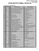
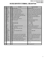
MICROCOMPUTER’S TERMINAL DESCRIPTION
Pin No.
Pin Name
I/O
Purpose / Description
Processing Operation
1
/RST0
O
ATAPI I/F controller / DVD ROM decoder /reset output terminal
Reset terminal 104PIN of IC250 (Active L)
2
/RST1
O
CD/DVD Servo / Data processor reset output terminal
Reset terminal 48PIN of IC201 (Active L)
3
SPSTBY
O
Spindle motor driver power save output terminal
VM1 (spindle motor) control
7
MD2
I
Operation mode change input terminal
Connected to +5V
9
FLCNT
O
Flash memory write-in circuit ON output terminal
Control of Q151
10
SB
O
Spindle motor short brake output terminal
VM1 (spindle motor) control
12
VSS
-
GND
Connected to GND
14-20 D0-D7
I/O
CPU data bus terminal
IC201 and IC250 control data bus
21
VCC
-
Power supply input terminal
Connected to +5V
22-28 HA0-HA6
O
CPU address bus terminal
IC201 and IC250 address bus
30
VSS
-
GND
Connected to GND
31
SWA
I
Loading mechanism SWA input terminal
Connected to +5V
32
SWB
I
Loading mechanism SWB input terminal
Connected to +5V
33
LOEJKEY
I
Loading/eject key input terminal
Connected to +5V
34
INSIDE
I
Pickup inside detection (SW4) input terminal
Active L
37
CSEL
I
IDE cable selection input terminal
CSEL (7PIN) control signal of IC250
38
SWC
I
Loading mechanism SWC input terminal
Connected to +5V
40
/SRVDPCS
O
Servo / Data processor selection output terminal
SDCS (44PIN) selection control signal of IC201
41
/ATACS
O
ATAPI I/F controller / DVD ROM decoder selection output terminal
ATACS (98PIN) selection control signal of IC250
43
PCS
O
VRCK frequency demultiplier output terminal (RF AMP )
PSC (50PIN) control signal of IC101
44
MD0
I
Operation mode change input terminal
Connected to +5V
45
MD1
I
Operation mode change input terminal
Connected to GND
47
/STBY
I
CPU standby input terminal
Connected to +5V
48
/RES
I
CPU reset input terminal
System reset input of IC151 (ActiveL)
Connected to GND
Connected to GND
Crystal input terminal
X151 16MHz
Crystal input terminal
X151 16MHz
Connected to +5V
Lead control terminal
The bus control output of IC201 and IC250
Write control terminal
The bus control output of IC201 and IC250
Flash memory rewriting permission input
-
58
AVSS
-
GND
Connected to GND
59
FE
I
Focus error input terminal
-
60
LVL
I
Sub beam signal input terminal
-
61-64 TEST0-TEST3
I
Test mode input terminal
Not used for after service
65
TESTCNT
I
Temperature sensor input terminal
-
67
AVCC
-
Power supply input terminal
Connected to +5V
68
/ATAINT
I
ATAPI I/F controller / DVD ROM decoder request signal input terminal
Request signal input from 102PIN of IC250
IC151 (MAIN UNIT : SERVO CONTROL)
www. xiaoyu163. com
QQ 376315150
9
9
2
8
9
4
2
9
8
TEL 13942296513
9
9
2
8
9
4
2
9
8
0
5
1
5
1
3
6
7
3
Q
Q
TEL 13942296513 QQ 376315150 892498299
TEL 13942296513 QQ 376315150 892498299

