


14
|
English
CD/External disc control features
Playing CD
When there is no disc inserted
1
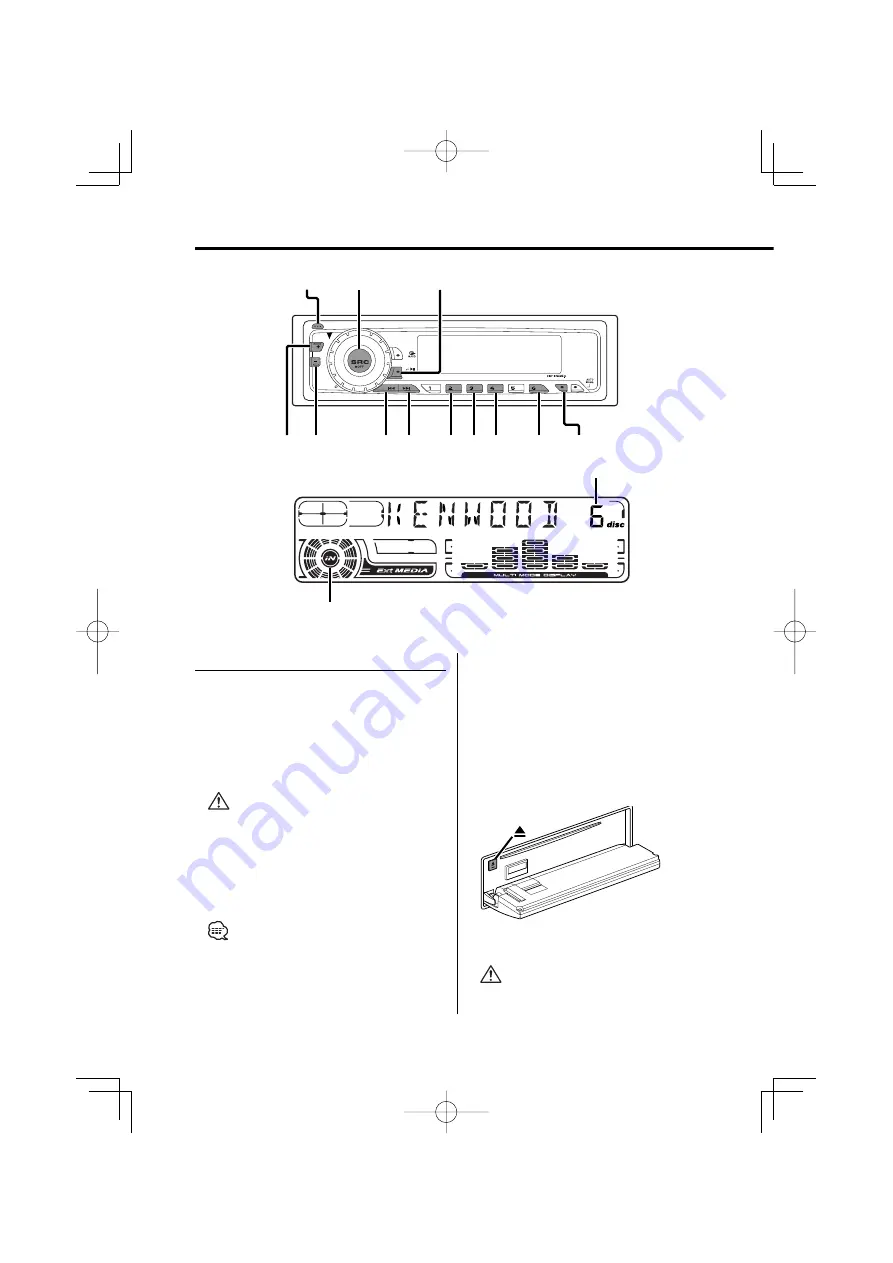
Drop open the faceplate
Press the Release button.
2
Insert a disc.
3
Press the faceplate on the left side, and
return it to its former position.
• When the faceplate has been dropped open, it might
interfere with the shift lever or something else. If this
happens, pay attention to safety and move the shift
lever or take an appropriate action, then operate the
unit.
• Do not use the unit with the faceplate in the open
condition. If it's used in the open position dust can
enter the inside part and cause damage.
• When a disc is inserted, the "IN" indicator is ON.
When a disc is inserted
Press the [SRC] button.
Select the "CD" display.
Pause and play
Press the [
38
] button.
Each time the button is pressed it pauses and
plays.
Eject the disc
1
Drop open the faceplate
Press the Release button.
2
Eject the disc
Press the [
0
] button.
3
Press the faceplate on the left side, and
return it to its former position.
• 3 in. (8cm) disc can't be played. Using an adapter and
inserting them into this unit can cause damage.
FM
SCAN
RDM
REP
M.RDM
AM
DISP
SCAN
M.RDM
RDM REP
38
DISC–
DISC+
¢
4
SRC
Release button
Disc number
IN indicator
KDC-5026̲M̲2697̲U.S̲r2.Indd 14
03.10.8, 10:18:30 AM


