background image

4

English

Controls

MONO(Lch)

STEREO

OPERATION

A.CH

B.CH

FILTER

A.CH HPF

FILTER FREQUENCY(Hz)

LPF

OFF

HPF

HPF

OFF

B.M.S.

+12dB

OFF

REMOTE

INPUT SELECTOR

GND

EXT.AMP.CONT.

LINE IN

L

R

L

R

A

B

SUB

B

A

B

A

A

SUB

200

50

B.CH HPF

200

50

B.CH LPF

200

50

SUB.CH LPF

200

50

MONO(Lch)

STEREO

OPERATION

A.CH

B.CH

FILTER

A.CH HPF

FILTER FREQUENCY(Hz)

LPF

OFF

HPF

HPF

OFF

B.M.S.

+12dB

OFF

REMOTE

INPUT SELECTOR

B

A

B

A

A

SUB

200

50

B.CH HPF

200

50

B.CH LPF

200

50

SUB.CH LPF

200

50

8

0

9

1

4

6

5

3

7

2

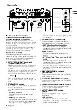
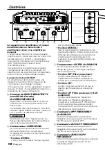
The unit is a 5-channel amplifier
incorporating 2 stereo amplifiers and 1
monaural amplifier in a single body.

The stereo amplifier on one side is called
amplifier A, while the one on the other side is
amplifier B. The monaural amplifier is called
the amplifier SUB.
This unit is compatible with a large variety of
systems by combining the switches and
functions described in the following.

About D-class (SUB.CH)

A D-class amplifier uses an inaudible
frequency as a switching pulse to change the
pulse width to represent the music signal.
(Pulse Width Modulation: P.W.M.)

8

INPUT SENSITIVITY control
(A.CH/B.CH/SUB.CH) 

Adjust this control according to the pre-out
level of the center unit connected to this
amplifier.
The sensitivities of amplifiers A, B and SUB
can be adjusted independently regardless
of the position of the input selector switch.

Refer to "Specifications" on the center
unit’s instruction manual about the pre-out
level.

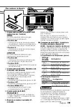
5

OPERATION switch

This switch is used to select the operation
mode of the amplifier.
This setting is valid for both the amplifier A
and B.

• STEREO position:

The amplifier can be used as a stereo
amplifier.

• MONO (Lch) position:

Amplifies the signal input from the left side
only. Set to this position and make bridged
connections to use as a high-power

monaural amplifier. (The input right signal is
not output.)

1

FILTER switch (A.CH/B.CH)

This switch allows to apply high-pass or
low-pass filtering to the speaker outputs.

• HPF (High-Pass Filter) position:

The filter outputs the band of higher
frequencies than the frequency set with the
HPF FREQUENCY control.

• OFF position:

The entire bandwidth is output without
filtering.

• LPF (Low-Pass Filter) position: (B.CH

only)

The filter outputs the band of lower
frequencies than the frequency set with the
LPF FREQUENCY control.
The speaker output is automatically turned
monaural (L+R) and the bass boost function
is activated.

2

HPF FREQUENCY control
(A.CH/B.CH)

Sets the cutoff frequency when the FILTER
switch is set to HPF.

4

B.CH LPF FREQUENCY control 

Sets the cutoff frequency when the FILTER
switch is set to LPF.

6

SUB.CH LPF FREQUENCY control 

This control adjusts the frequency band
output from this amplifier SUB.

7

INPUT SELECTER switch
(AB/A)

This switch toggles the input signal of
amplifier B.

• AB position:

The input for terminal A is output from
amplifier A, while the input for terminal B is
output from amplifier B.

NOTE

Summary of Contents for KAC-PS650D

Page 1: ...ead through this instruction manual Familiarity with installation and operation procedures will help you obtain the best performance from your new power amplifier For your records Record the serial number found on the back of the unit in the spaces designated on the warranty card and in the space provided below Refer to the model and serial numbers whenever you call upon your KENWOOD dealer for in...

Page 2: ...tallation consult your Kenwood dealer If the unit does not seem to be working right consult your Kenwood dealer FCC WARNING This equipment may generate or use radio frequency energy Changes or modifications to this equipment may cause harmful interference unless the modifications are expressly approved in the instruction manual The user could lose the authority to operate this equipment if an unau...

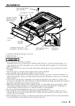
Page 3: ... block the cooling fan openings when installing the unit Blocking these openings will inhibit the cooling of the internal temperature and result in malfunction When making a hole under a seat inside the trunk or somewhere else in the vehicle check that there is nothing hazardous on the opposite side such as a gasoline tank brake pipe or wiring harness and be careful not to cause scratches or other...

Page 4: ...o Specifications on the center unit s instruction manual about the pre out level 5 OPERATION switch This switch is used to select the operation mode of the amplifier This setting is valid for both the amplifier A and B STEREO position The amplifier can be used as a stereo amplifier MONO Lch position Amplifies the signal input from the left side only Set to this position and make bridged connection...

Page 5: ...olor button Select the ON color for the indicator Every time the button is pressed 7 fixed colors and the variable color change The color can t be set when the indicator is blinking Controlling the B M S from the Kenwood center unit B M S Bass management system When the B M S switch is set in the remote position the bass boost amount and frequency offset can be controlled from the center unit Bass...

Page 6: ...e below times When the vehicle battery is weak When the battery capacity is low When the battery cord is worn When the battery wire is too small or too long and can t supply enough current The color blinks purple When the unit has failed and direct current voltage is generated to the speaker s output Turn the power OFF and release the protection If the indicator doesn t quit blinking contact your ...

Page 7: ...e speakers to be connected should have an impedance of 4Ω or greater When multiple speakers are to be connected ensure that the combined impedance is 4Ω or greater The rated input of the speakers should be no less than the maximum output of the amplifier Otherwise malfunction may result Amplifier SUB speaker output terminal As this unit accepts speakers with a minimum impedance of 2 ohms connect s...

Page 8: ...t the negative terminal of the battery If sound is not output normally immediately turn power off and check connections Be sure to turn the power off before changing the setting of any switch If the fuse blows check wires for shorts then replace the fuse with one of the same rating Check that no unconnected wires or connectors are touching the car body Do not remove caps from unconnected wires or ...

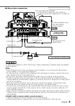
Page 9: ... unit s fuse capacity Use a power wiring cord with a diameter of 8 mm2 AWG 8 or greater When more than one power amplifier are going to be used use a power supply wiring wire and protective fuse of greater current handling capacity than the total maximum current drawn by each amplifier EXT AMP CONT external amplifier control terminal 1 Peel the cladding of wire for a length of 11mm from the end 2 ...

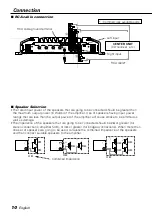
Page 10: ...ng to be connected should be greater than the maximum output power in Watts of the amplifier Use of speakers having input power ratings that are less than the output power of the amplifier will cause smoke to be emitted as well as damage The impedance of the speakers that are going to be connected should be 2Ω or greater for stereo connections amplifier SUB or 4Ω or greater for bridged connections...

Page 11: ...TPUT POWER IN P CON BATT GND FUSE 30Ax2 LEFT BRIDGED RIGHT SUB SUB A B English 11 Speaker wire connection Lead terminal Stereo Connections Rear Left speaker Rear Right speaker Bridged Connections Subwoofer L R Front Left speaker Front Right speaker Left speaker Bridged Right speaker Bridged Subwoofer L R ...

Page 12: ...OR B A B A A SUB 5 7 L R L R L R A B SUB MONO Lch STEREO OPERATION INPUT SELECTOR B A B A A SUB 5 7 L R L R L R L R L R A B SUB B A SUB A CH B CH FILTER LPF OFF HPF HPF OFF 1 MONO Lch STEREO OPERATION INPUT SELECTOR B A B A A SUB 5 7 L R L R L R A B SUB MONO Lch STEREO OPERATION INPUT SELECTOR B A B A A SUB 5 7 CENTER UNIT CENTER UNIT CENTER UNIT 5 channel system Front Right speaker Front Left spe...

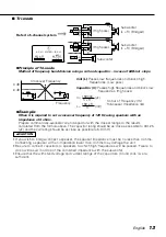
Page 13: ...of 120 Hz using speakers with an impedance of 4 ohms Prepare commercially available coil and capacitor with the closest ratings to the results calculated from the formula above The capacitor rating should be as close as possible to 331 25 µF and the coil rating should be as close as possible to 5 3 mH If you wish to bridge connect a speaker the speaker impedance must be no less than 4 ohms Connect...

Page 14: ...is not set to the correct position The speakers wire are connected with wrong polarity A speaker wire is pinched by a screw in the car body The switches may be set improperly The B M S switch setting is incorrect The external amplifier control wire has come loose Connect the input or output cables Check connections by referring to Indicator Replace the fuse and use lower volume After check the spe...

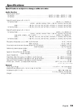
Page 15: ... Frequency Response 0 3 dB A B channel 5 Hz 70 kHz Frequency Response 0 3 dB SUB channel 15 Hz 200 Hz Total Harmonic Distortion Rated power A B channel 0 006 1 kHz Total Harmonic Distortion Rated power SUB channel 0 2 100 Hz Sensitivity rated output MAX 0 2 V Sensitivity rated output MIN 5 0 V Signal to Noise Ratio A B channel 105 dB Signal to Noise Ratio SUB channel 100 dB Input Impedance 10 kΩ H...

Page 16: ... d un fusible d une valeur différente peut être la cause d un mauvais fonctionnement de votre appareil Pour éviter les courts circuits lors du remplacement d un fusible déconnectez d abord le faisceau de câbles Si vous rencontrez des problèmes pendant l installation consultez votre revendeur Kenwood Si l appareil semble ne pas fonctionner correctement consultez votre revendeur Kenwood Cet appareil...

Page 17: ... que les ouães d aération ne soient pas obstruées En effet si la chaleur interne ne peut pas être éliminée par la ventilation de l appareil une anomalie de fonctionnement peut aisément survenir Lors du forage d un trou sous le siège à l intérieur du coffre ou partout ailleurs dans le véhicule vérifier s il n y a pas d élément dangereux de l autre côté tel qu un réservoir à carburant une conduite d...

Page 18: ...st amplifié Utiliser cette position et effectuer les pontages pour disposer d un amplificateur monaural de plus forte puissance Le signal d entrée droite n est pas reproduit 1 Commutateur FILTER A CH B CH Ce commutateur permet d effectuer un filtrage des graves ou des aigus appliqués vers les haut parleurs Position HPF Filtre passe haut Le filtre laisse passer les fréquences supérieures à la fréqu...

Page 19: ...iable V COLOR Sélectionner la couleur correspondant à ON pour l indicateur Dès lors que l on appuie sur le bouton 7 couleurs fixes ainsi que la couleur variable changent La couleur ne peut pas être réglée lorsque l indicateur clignote Commande du B M S à partir de l unité principale Kenwood B M S Système de Contrôle des Graves Lorsque l interrupteur du B M S est réglé sur la position télécommande ...

Page 20: ... La raison peut être la suivante La batterie du véhicule est faible La capacité de la batterie est trop basse Le cordon de la batterie est usé Le fil électrique de la batterie est trop court ou trop long et le courant amené est insuffisant La couleur violette clignote Lorsque l unité est en panne et que l intensité du courant continu est transmise à la sortie haut parleur Eteindre l appareil puis ...

Page 21: ... supérieure Lorsque plusieurs haut parleurs doivent être connectés s assurer que l impédance combinée soit de 4 ohms ou supérieure La puissance admissible par les haut parleurs doit être au moins égale à la puissance de sortie de l amplificateur Dans le cas contraire une anomalie de fonctionnement peut survenir Borne SUB SPEAKER OUTPUT Cet appareil étant conçu pour fonctionner avec une impédance d...

Page 22: ...ion et vérifier tous les raccordements Veiller à mettre l appareil hors tension avant de changer la position des commutateurs Si le fusible saute vérifier si les câbles ne sont pas court circuités et remplacer le fusible par un autre fusible de même capacité nominale Vérifier qu aucun câble ou connecteur non raccordé ne touche la carrosserie de la voiture Ne pas retirer les capuchons des câbles ou...

Page 23: ...re au pouvoir de coupure du fusible de l unité Utiliser un cordon d alimentation d un diamètre égal ou supérieur à 8 mm2 AWG 8 Lorsque plus d un amplificateur de puissance doivent être utilisés utiliser un câble de câblage d alimentation et un fusible de sécurité dont la limite de tension est supérieure au courant total maximum tiré par chaque amplificateur Borne EXT AMP CONT Contrôle de l amplifi...

Page 24: ... l amplificateur L utilisation d haut parleur dont la puissance d entrée nominale est inférieure à la puissance de sortie de l amplificateur entraînera l émission de fumée ainsi que des dommages L impédance des haut parleur qui vont être connectées doit être de minimum 2Ω pour les connexions stéréo amplificateur SUB ou de minimum 4Ω pour des connexions pontées Lorsque plus d un jeu d haut parleur ...

Page 25: ...IDGED RIGHT SUB SUB A B Frençais 25 Connexion des câbles d haut parleur Cosse pour câble Connexions stéréo Connexions en pont Haut parleur avant droit Haut parleur avant gauche Haut parleur arrière gauche Haut parleur arrière droit Haut parleur droit Pont Haut parleur gauche Pont Haut parleurs d extrêmes graves G D Haut parleurs d extrêmes graves G D ...

Page 26: ...O OPERATION INPUT SELECTOR B A B A A SUB 5 7 L R L R L R L R L R A B SUB B A SUB A CH B CH FILTER LPF OFF HPF HPF OFF 1 MONO Lch STEREO OPERATION INPUT SELECTOR B A B A A SUB 5 7 L R L R L R A B SUB MONO Lch STEREO OPERATION INPUT SELECTOR B A B A A SUB 5 7 Unité centrale Système 5 canaux Système 3 canaux Haut parleur droit Pont Haut parleur gauche Pont Système 4 canaux Haut parleurs d extrêmes gr...

Page 27: ...l faut établir la fréquence de transition à 120 Hz en utilisant des haut parleurs ayant une impédance de 4 ohms Se procurer dans le commerce la bobine et le condensateur présentant des caractéristiques aussi proches que possible des valeurs calculées Dans ce cas la condensateur doit avoir une capacité aussi proche que possible de 331 25 µF et le bobine une capacité aussi proche que possible de 5 3...

Page 28: ...ccordés en inversant la polarité Un câble de haut parleur est pincé par une vis dans le châssis de la voiture Les commutateurs ne sont peut être pas positionnés comme il convient La configuration de l interrupteur du B M S est incorrecte Le cordon du contrôle de l amplificateur extérieur s est relâché Brancher les câbles d entrée ou de sortie Vérifier les raccordements en se reportant au paragraph...

Page 29: ...0 Hz 0 5 D H T Réponse en fréquence 0 3 dB A B canaux 5 Hz 70 kHz Réponse en fréquence 0 3 dB SUB canal 15 Hz 200 kHz Distorsion harmonique totale puissance nominale A B canaux 0 006 1 kHz Distorsion harmonique totale puissance nominale SUB canal 0 2 100 Hz Sensibilité Max 0 2 V puissance nominale Sensibilité Min 5 0 V puissance nominale Rapport signal bruit A B canaux 105 dB Rapport signal bruit ...

Page 30: ...rescrito El uso de un fusible de régimen incorrecto podría ocasionar un funcionamiento defectuoso de la unidad Para evitar cortocircuitos mientras sustituye el fusible desconecte previamente el mazo de conductores Si tiene problemas durante la instalación consulte con su distribuidor Kenwood Si la unidad no está funcionando correctamente consulte con su distribuidor Kenwood Limpieza de la unidad S...

Page 31: ...res de enfriamiento cuando instale la unidad Al tapar estas aberturas no podrá reducirse adecuadamente la temperatura interior y podrá producirse un fallo en el funcionamiento Cuando haga un orificio bajo el asiento o en el portaequipajes o en algún otro lugar del vehículo verifique que no existan objetos peligrosos al lado opuesto tales como un tanque de gasolina tubo del freno o los alambres del...

Page 32: ...nta la posición del conmutador selector de entrada Referir a Especificaciones del manual de instrucciones de la unidad central con respecto al nível de presalida 5 Conmutador de funcionamiento OPERATION Este conmutador permite seleccionar el método de amplificación de las señales de entrada Este valor es válido tanto para el amplificador A y B Posición STEREO Las señales de entrada derecha e izqui...

Page 33: ...M S FREQUENCY Cuando el interruptor B M S se ajusta en 12dB REMOTE se ajusta la frecuencia central potenciada 9 Botón de color variable V COLOR Seleccione el color ON para el indicador Cada vez que pulsa el botón los 7 colores fijos y el color variable cambian El col0or no puede ajustarse cuando el indicador parpadea Control del B M S desde la unidad central Kenwood B M S Sistema de gestión de baj...

Page 34: ...ando la batería del vehículo está débil Cuando la capacidad e la batería es baja Cuando el cable de la batería está desgastado Cuando el cable de la batería es demasiado pequeño o largo y no puede suministrar corriente suficiente Parpadea en púrpura Cuando la unidad ha fallado y se genera tensión de corriente directa hacia la salida del altavoz DESCONECTE la alimentación y liere la protección Si e...

Page 35: ...er una impedancia de 4 ohmios o mayor Cuando vaya a conectar múltiples altavoces asegúrese de que la impedancia combinada sea de 4 ohmios o mayor La entrada nominal de los altavoces no deberá ser inferior a la salida máxima del amplificador De lo contrario podría producirse una falla en el funcionamiento Terminal SUB SPEAKER OUTPUT Como este aparto acepta altavoces con una impedancia mínima de 2 o...

Page 36: ...compruebe las conexiones No se olvide de desconectar la alimentación antes de cambiar el ajuste de cualquier conmutador Si el fusible se quema compruebe que no haya un cortocircuito en los cables luego cambie el fusible por uno que tenga el mismo amperaje Verifique que ninguno de los cables o conectores que están sin conectar se encuentren tocando la carrocería del automóvil No retire las tapas de...

Page 37: ...unidad Utilice un cable de corriente con un diámetro de 8 mm2 AWG 8 o mayor Cuando desee utilizar más de un amplificador de potencia utilice un cable de suministro de alimentación y un fusible de protección de una capacidad de soporte de corriente mayor a la corriente máxima total utilizada por cada amplificador Terminal de control de amperaje de salida EXT AMP CONT 1 Pele el revestimiento del cab...

Page 38: ...cten al amplificador debe ser mayor que la potencia de salida máxima en Wats del amplificador Utilizar altavoces que posean potencias de entrada menores a la salida de entrada del amplificador producirá emisiones de humo y daños La impedancia de los altavoces que se conecten al amplificador debe ser de 2Ω o más para conexiones estéreo amplificador SUB o de 4Ω o más para las conexiones en puente Cu...

Page 39: ...T SUB SUB A B Español 39 Conexión del cable de los altavoces Terminal de cable Conexiones estereofónicas Conexiones en puente Altavoz derecho Puenteada Altavoz izquierdo Puenteada Altavoz delantero izquierdo Altavoz delantero derecho Altavoz trasero derecho Altavoz trasero izquierdo Altavoz de subgraves izquierdo derecho Altavoz de subgraves izquierdo derecho ...

Page 40: ...R B A B A A SUB 5 7 L R L R L R L R L R A B SUB B A SUB A CH B CH FILTER LPF OFF HPF HPF OFF 1 MONO Lch STEREO OPERATION INPUT SELECTOR B A B A A SUB 5 7 L R L R L R A B SUB MONO Lch STEREO OPERATION INPUT SELECTOR B A B A A SUB 5 7 Aparato Central Aparato Central Aparato Central Aparato Central Aparato Central Aparato Central Aparato Central Sistema de 5 canales Sistema de 3 canales Sistema de 4 ...

Page 41: ...Hz utilizando altavoces con una impedancia de 4 ohmios Prepare una bobina y un capacitor de venta en el comercio del ramo que tengan unas especificaciones nominales lo más parecidas a los resultados calculados en la fórmula de arriba Las especificaciones nominales del capacitor deberán ser lo más parecido posible a 331 25 µF y las especificaciones nominales de la bobina deverán ser lo más parecido...

Page 42: ...da no está en la posición correcta Los cables de los altavoces están conectados con las polaridades invertidas Un cable de altavoz está pellizcado por un tornillo de la carrocería del automóvil Los conmutadores pueden estar mal ajustados El ajuste del interruptor B M S es incorrecto Se ha aflojado el cable del controlador del amplificador externo Conecte los cables de entrada o salida Compruebe la...

Page 43: ... 0 5 de distorsión armónica total 100 Hz 0 8 de distorsión armónica total Modo de 3 canales 4 Ω 120 W 2 130 W 1 1 kHz 0 5 de distorsión armónica total 100 Hz 0 5 de distorsión armónica total Respuesta de frecuencia 0 3 dB A B canales 5 Hz 70 kHz Respuesta de frecuencia 0 3 dB SUB canal 15 Hz 200 Hz Distorsión armónica total potencia nominal A B anales 0 006 1 kHz Distorsión armónica total potencia...

Page 44: ......

Reviews: