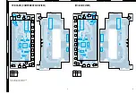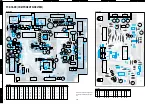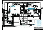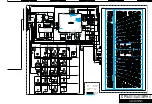
DPX-4010,4010/PH4
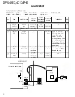
ADJUSTMENT
Set the controls and switches as follows.
BALANCE : Center position
BASS
: Center Position
LOUD : OFF
DOLBY NR : OFF
FADER
: Center position
TREBLE : Center position
METAL : OFF
OUTPUT
TUNER
ALIGNMENT
No.
ITEM
INPUT SETTINGS
SETTING
(RECEIVER)
POINTS
ALIGN FOR
FIG.
SETTINGS
FM SECTION
1
DISCRI-
98.1MHz
Connect a DC
FM
T
0V
(a)
MINATOR
0dev
voltmeter to TP
98.1MHz
F/E (TU100)
60dB
µ
(ANT input)
F/E (TU100)
CASSETTE DECK SECTION
[1]
AZIMUTH
MTT-902
–
–
Head Azimuth
Playing the mirror tape in
(b)
(1/2)
Mirror Tape
Screw
FWD mode, rotate screw
(A) and (B) so as to
eliminate a curl at the
guides on both ends of head
while looking into the mirror.
Play the tape in REV mode.
And make adjustment in the
same manner.
[2]
AZIMUTH
TCC-153
Connect a AC
PLAY
Head Azimuth
Adjust the azimuth for
(b)
(2/2)
10kHz, –10dB
voltmeter and
Screw
each Lch/Rch or FWD/RVS
oscilloscope
becomes maximum.
to pri out
[3]
PLAY BACK
TCC-130
Connect a
PLAY
VR200A (L)
300mV
(c)
LEVEL
AC voltmeter
VR200B (R)
to CN200
TU
100
VR200A
CN200
VR200B
R G L
(MAIN PWB UNIT)
(c) 300mV
AC voltmeter
Rch Lch
DC voltmeter
(a) 0V
T
TP
TU100
REV(B)
6
www. xiaoyu163. com
QQ 376315150
9
9
2
8
9
4
2
9
8
TEL 13942296513
9
9
2
8
9
4
2
9
8
0
5
1
5
1
3
6
7
3
Q
Q
TEL 13942296513 QQ 376315150 892498299
TEL 13942296513 QQ 376315150 892498299


