6
Fig. 1.1
2
3
4
5
1
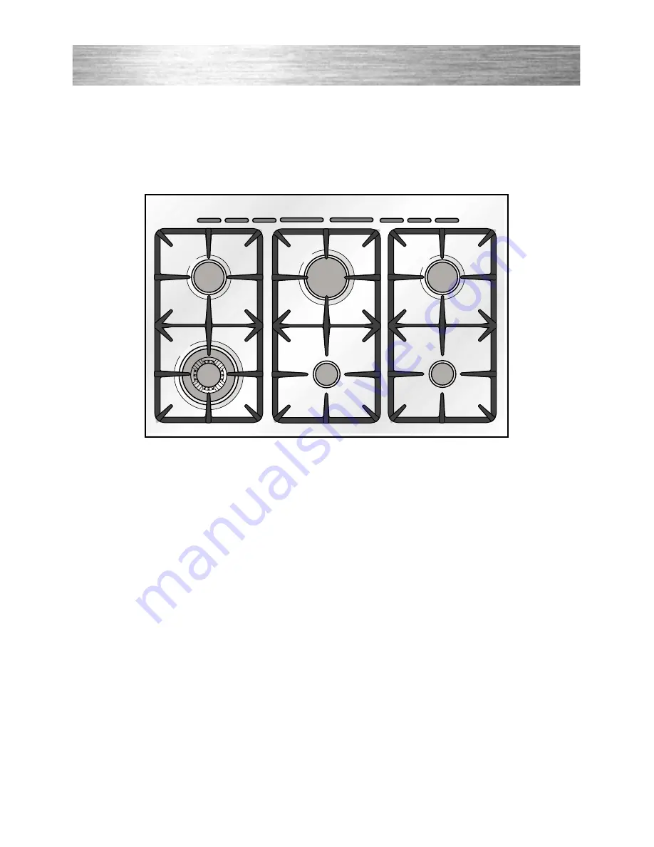
COOKING HOB
1. Triple-ring burner (TR)
3,50 kW
2. Semi-rapid burner (SR)
1,75 kW
3. Rapid burner (R)
3,00 kW
4. Auxiliary burner (A)
1,00 kW
5. Semi-rapid burner (SR)
6. Auxiliary burner (A)
1 - COOKING HOB
Page 1: ...Instructions for use Installation advice DUAL FUEL DOUBLE OVEN COOKER CK 410 ...
Page 2: ...2 ...
Page 3: ...n 34 39 Electrical section 40 41 Guarantee 42 After Sales Service 43 Read the instructions carefully before installing and using the appliance CAUTION this appIiance must only be installed in a permanently ventilated room in compliance with the applicable regulations This cooker has been designed constructed and marketed in compliance with safety requirements of EEC Directive Gas 90 396 safety req...
Page 4: ... be void if the appliance is used within a non domestic environment i e a semi commercial commercial or communal environment FIRST USE OF THE OVEN Follow the instructions below Furnish the interior of the oven by placing the wire racks as described in Cleaning and maintenance Insert shelves and tray Switch the empty oven on to max to eliminate grease from the heating ele ments See pages 11 and 16 ...
Page 5: ...upplied with a protective film on steel and aluminium parts This film must be removed before using the appliance WARNING When correctly installed your product meets all safety requirements laid down for this type of product catego ry However special care should be taken around the rear or the under neath of the appliance as these areas are not designed or intended to be touched and may contain sha...
Page 6: ... 3 4 5 6 1 COOKING HOB 1 Triple ring burner TR 3 50 kW 2 Semi rapid burner SR 1 75 kW 3 Rapid burner R 3 00 kW 4 Auxiliary burner A 1 00 kW 5 Semi rapid burner SR 1 75 kW 6 Auxiliary burner A 1 00 kW 1 COOKING HOB ...
Page 7: ...9 Electronic programmer Main oven only 10 Conventional oven temperature knob 11 Conventional oven switch knob Pilot lamps 12 Main oven temperature indicator light 13 Conventional oven temperature indicator light 2 CONTROL PANEL 4 11 10 13 Please note This appliance incorporates a safety cooling fan which you will hear operat ing whenever the oven or grill are in use This fan may continue to run fo...
Page 8: ...iquids whereas the minimum set ting allows slower warming of food or maintaining simmering conditions of liq uids Other intermediate operating can be achieved by positioning the control knob indicator between the maximum and minimum setting but not between the maximum and off positions LIGHTING THE BURNERS To ignite the burner 1 Lightly press and turn the knob anti clockwise and position the knob ...
Page 9: ...rol panel near each knob there is a diagram that indicates which burner is controlled by that knob Select the burner that is most suitable for the diameter and capacity of the pan to be used As an indication the burners and the pans must be used in the following way It is important that the base diameter of the pot is at least the same diameter as the burner ring to obtain an efficient heat transf...
Page 10: ...n support When using a WOK always place the supplied stand in position over the burner to main tain the correct operation of the triple ring burner Fig 3 5a 3 5b IMPORTANT The special grille for wok pans fig 3 5b MUST BE PLACED ONLY over the pan rest for the triple ring burner Fig 3 5a WRONG Fig 3 5b CORRECT ...
Page 11: ...ories with warm water and washing up liquid WARNING The door is hot use the handle OPERATING PRINCIPLES Heating and cooking in the MULTI FUNCTION oven are obtained in the fol lowing ways a by normal convection The heat is produced by the upper and lower heating elements b by forced convection The circular heating element and fan constantly circulate heated air over the food in the oven for a more ...
Page 12: ... turn ON or OFF automatically according to the energy need which is determined by the thermostat OVEN LIGHT By setting the knob to this position only the oven light comes on 15 W The light remains on whilst any of the cooking modes are selected TRADITIONAL CONVECTION COOKING The upper and lower heating elements are switched on The heat is diffused by natural convection and the temperature must be ...
Page 13: ...ng etc HOT AIR COOKING The circular element and the fan are on The heat is diffused by forced convection and the temperature must be set between 50 and 250 C It is not necessary to preheat the oven Recommended for For foods that must be well done on the outside and tender or rare on the inside i e lasagna lamb roast beef whole fish etc DEFROSTING FROZEN FOODS Only the oven fan is on To be used wit...
Page 14: ...en 50 and 175 C for max 30 minutes It is necessary to preheat the oven for about 5 minutes Use with the oven door closed Attention the oven door becomes very hot during operation Keep children away For correct use see GRILLING AND AU GRATIN Recommended for For grill cooking when a fast outside browning is necessary to keep the juices in i e veal steak steak hamburger etc CONVECTION COOKING WITH VE...
Page 15: ...DVICE SIMULTANEOUS COOKING OF DIFFERENT FOODS The MULTI FUNCTION oven set on position and gives simultaneous cooking of different foods Different foods such as fish cake and meat can be cooked together without mixing the smells and flavours This is possible since the fats and vapors are oxidized while passing through the electrical element and therefore are not deposited onto the foods The only pr...
Page 16: ...ttention the oven door becomes very hot during operation Keep children away 5 CONVENTIONAL OVEN GENERAL FEATURES The conventional oven has 3 heating elements which are Top element 700 W Bottom element 800 W Grill element 1450 W NOTE Upon first use it is advisable to operate the oven at the maximum temperature thermostat knob on position 250 for 60 minutes in the position and for another 15 minutes...
Page 17: ...ense grilling browning cooking au gratin and toasting etc It is recommended that you do not grill for longer than 30 minutes at any one time Attention the oven door becomes very hot during operation Keep children away USE OF THE GRILL Preheat the oven for about 5 minutes Introduce the food to be cooked positioning the rack as close to the grill as possible The drip pan should be placed under the r...
Page 18: ...Y Bread Loaf 500g Flour wt 225 7 8 20 25 mins Bread Rolls 225 7 8 10 15 mins Pizza Dough 225 8 15 20 mins Shortcrust pastry 200 6 20 30 mins Quiches Flans 180 190 4 5 30 40mins ROAST MEATS Beef medium joint 190 5 20 25 mins lb 20mins Lamb 190 5 25 30mins lb 25mins Pork 190 5 30mins lb 30mins Chicken 190 5 20 25mins lb 30mins Turkey 180 4 15 20mins lb 20mins Stews Casseroles 170 3 11 2 2hours Tempe...
Page 19: ...with the buttons one hand operation A power cut makes the clock go to zero and cancels the set programs Description of the buttons Timer Cooking time End of cooking time Manual position and cancellation of the set cooking program Advance the time for of all pro grams Decrease the program time and changing the frequency of the audi ble signal The electronic programmer performs the following functio...
Page 20: ... the desired time in the panel fig 7 4 Having finished the setting the clock hour will appear on the panel and the symbol will be lit The countdown will start immediately and may be seen at any moment on the panel by simply pressing the button At the end of the time the symbol will be switched off and an intermittent buzzer will go off this can be stopped by pressing any of the buttons SETTING THE...
Page 21: ...panel Fig 7 6 Fig 7 5 AUTOMATIC OVEN COOKING To cook food automatically in the oven it is necessary to 1 Set the length of the cooking time 2 Set the end of the cooking time 3 Set the temperature and the oven cooking program These operations are done in the follow ing way 1 Set the length of time you need to cook the food by pushing the but ton and the button to advance or to go back if you have p...
Page 22: ...ime you need to cook the food by pushing the but ton and the button to advance or to go backwards Fig 7 7 This sets the desired stop time or 2 Set the time you need the food to stop cooking by pushing the button and the button to advance or to go backwards if you have passed the desired time Fig 7 8 AUTO and the symbol will be on Then set the temperature and the cook ing program see the relevant s...
Page 23: ...th a soft cloth Acidic substances like lemon juice tomato sauce vinegar etc can damage the enamel if left in contact for too long REPLACING THE OVEN LIGHT BULB Switch the cooker off at the mains When the oven is cool unscrew and replace the bulb with another one resistant to high temperatures 300 C voltage 230 V 50 Hz 15 W E14 Note Oven bulb replacement is not covered by your guarantee STAINLESS S...
Page 24: ...mage to the electric ignition do not use it when the burn ers are not in place CORRECT REPLACEMENT OF THE BURNERS It is very important to check that the burner flame distributor F and the cap C has been correctly positioned see figs 8 1 8 2 failure to do so can cause a poor burner flame and or damage to the burner and hob Check that the electrode S fig 8 1 is always clean to ensure trouble free sp...
Page 25: ...ust be correctly positioned see fig 8 3 the burner rib must be enter in their logement as shown by the arrow The burners must be correctly positioned so that they cannot rotate fig 8 4 Then position the cap A and the ring B fig 8 4 8 5 Fig 8 3 Fig 8 4 A B ...
Page 26: ...be easily removed for cleaning by unscrewing the 2 retaining screws Fig 8 6 Do not store flammable material in the oven or in the storage com partment STORAGE COMPARTMENT The storage compartment is accessible through the pivoting panel fig 8 7 Fig 8 6 ...
Page 27: ...the safety catch which stops it sliding out faces the inside of the oven To dismantle operate in reverse order Fig 8 8 Fig 8 9 INSIDE OF OVEN This must be cleaned after every use Remove and refit the side runner frames as described on the next chapter With the oven warm wipe the inside walls with a cloth soaked in very hot soapy water or another suitable product Side runner frames tray and rack ca...
Page 28: ...nges fig 8 10B Hold the door as shown in fig 8 10 Gently close the door and withdraw the lower hinge pins from their location fig 8 10C Withdraw the upper hinge pins from their location fig 8 10D Rest the door on a soft surface To replace the door repeat the above steps in reverse order Fig 8 10D Fig 8 10C Fig 8 10B Fig 8 10A REMOVING THE OVEN DOOR Fig 8 10 ...
Page 29: ... to observe this rule will invalidate the warranty The electrical mains outlet if located behind the cooker must not be higher than 18 cm above the floor level Some appliances are supplied with a protective film on steel and aluminium parts This film must be removed before using the cooker USABLE lit 35 USABLE lit 60 900 600 900 920 Advice for the installer ...
Page 30: ... stated below If the cooker is located on a pedestal it is necessary to provide safety measures to prevent falling out The cooker must be installed by a qualified technician and in compliance with local safety standards 650 mm 500 mm 450 mm 50 mm Fig 9 1 This cooker has class 2 1 overheating protection so that it can be installed next to a cabinet If the cooker is installed adjacent to furniture w...
Page 31: ... the rear of the cooker on a piece of the polystyrene packag ing exposing the base for the fit ting of the feet Fit the 4 legs by screwing them tight into the support base as shown in picture 9 3 Fig 9 3 LEVELLING THE COOKER The cooker may be levelled by screwing the lower ends of the feet IN or OUT fig 9 4 Fig 9 4 ...
Page 32: ...le carry out this manoeuvre to prevent dam age to the adjustable feet fig 9 5 Fig 9 6 Fig 9 7 WARNING Be careful do not lift the cooker by the door handle when raising to the upright position fig 9 6 WARNING When moving cooker to its final position DO NOT DRAG fig 9 7 Lift feet clear of floor fig 9 5 ...
Page 33: ...ises the per manent opening shall be an air vent If there are other fuel burning appliances in the same room BS 5540 Part 2 1989 should be consulted to determine the requisite air vent requirements If the cooker is installed in a cellar or basement it is advisable to provide an air vent of effective area 100 cm2 irrespective of the room volume If the room or internal space containing these applian...
Page 34: ...lation of the cooker to Natural Gas or LP Gas must be carried out by a qualified gas engineer Installers shall take due account of the provisions of the relevant British Standards Code of Practice the Gas Safety Regulations and the Building Standards Scotland Consolidation Regulations issued by the Scottish Development Department INSTALLATION TO NATURAL GAS Installation to Natural Gas must conform...
Page 35: ...nce with BS669 part 1 and be of the correct construction for the type of gas being used The hose should not be crushed or trapped or be in contact with sharp or abrasive edges It should also not be subjected to corrosion by acidic cleansing agents The hose should also be connected in such away that it does not touch the floor NB Gas hoses designed for natural gas MUST NOT be used for supplying LPG...
Page 36: ...table spanners fig 10 2 After connection to the mains gas supply the couplings should be checked for gas soundness tightness as per current regulations for the gas type being used Fig 10 2 IMPORTANT PRESCRIPTIONS FOR GAS CONNECTION 700 mm Rear wall Suggested area for gas mains connection 200 mm Fig 10 3 ...
Page 37: ...t the injectors to be replaced according to the Table for the choice of the injectors page 39 To replace the injectors Remove the gratings the burner and the covers Using a wrench substitute the nozzle injectors J Fig 10 3 10 4 with those most suitable for the kind of gas for which it is to be used The burners are conceived in such a way so as not to require the regulation of the primary air CONVE...
Page 38: ...ith a quick turn from the maximum position to that of minimum The flame adjustment is done in the fol lowing way Turn on the burner Turn the tap to the MINIMUM position Take off the knob With a small flat screwdriver turn the screw inside the tap rod to the correct regulation fig 10 5 Normally for LPG tighten up the regula tion screw Fig 10 5 ...
Page 39: ... 0 45 32 65 97 Z Rapid R 3 00 0 75 42 85 115 Y Triple ring TR 3 50 1 50 65 95 135 T Nominal Power kW Reduced Power kW Ø injector 1 100 mm By pass 1 100 mm Ø injector 1 100 mm By pass 1 100 mm adjustable LUBRICATION OF THE GAS TAPS The operations must be executed by a qualified technician IMPORTANT All intervention regarding installation maintenance and conversion of the appli ance must be fulfille...
Page 40: ...en ing between the contacts of 3 mm between the appliance and the mains The power supply cable must not touch the hot parts and must be posi tioned so that it does not exceed 75 C at any point Once the appliance has been installed the switch or socket must always be accessible 11 ELECTRICAL SECTION IMPORTANT The cooker must be installed in accordance with the manufacturer s instructions Incorrect ...
Page 41: ... figure 11 1 Take up any slack in the cable and secure with the cable clamp D Replace the cover A N B The earth conductor must be left about 3 cm longer than the others Fig 11 1 D B PE A N L FEEDER CABLE SECTION TYPE HO5RR F 230 V 3 x 2 5 mm2 230 V PE N L1 L2 Fig 11 2 PE Earth N Neutral L Live TECHNICAL DATA 230 V AC 50 Hz Multi function Main oven Bottom element 1 40 kW Top element 1 00 kW Grill e...
Page 42: ... not misused neglected or damaged it it has not been modified it is not second hand it has not been used commercially you have not fitted a plug incorrectly and you supply your receipt to show when you brought it The appliance has been installed as per the instructions contained within this booklet This guarantee does not affect your statutory rights GUARANTEE ...
Page 43: ...t considering the characteristics of the models described here at any time and without notice to make eventual necessary modifications for their construction or for commercial needs If you require After Sales Service contact the MASTERCARE Domestic Appliance Helpline Telephone 08701 565550 Ser Nr AFTER SALES SERVICE ...
Page 44: ...code 1102364 ß4 Part Number 55160 ...