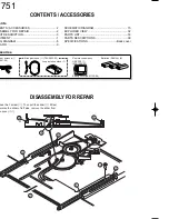
Batteries (R06/AA) (6)
FM indoor antenna (1)
(T90-0841-05)
AM loop antenna (1) (T90-0833-05)
Loop antenna stand (1)
Remote control assy
GRC-700 (1)
(A70-1300-05)
Battery cover(A09-1139-08)
ENTER
V
O
L
U
M
E
UP
DOWN
CONFIRM
ON/STANDBY
CONTRAST
Backlight
e
d
i t
m
o
v i
e
m
u
s i c
s
o
u
n d
li
s
te
n
m o d e
S
le
e p
C-V751
2
CONTENTS / ACCESSORIES
DISASSEMBLY FOR REPAIR
CONTENTS / ACCESSORIES .................................. 2
DISASSEMBLY FOR REPAIR....................................2
CIRCUIT DESCRIPTION ............................................3
ADJUSTMENT ............................................................7
WIRING DIAGRAM .....................................................8
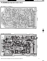
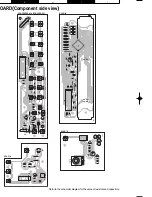
PC BOARD ................................................................ 9
SCHEMATIC DIAGRAM .......................................... 15
EXPLODED VIEW ....................................................32
PARTS LIST..............................................................33
PARTS DESCRIPTIONS ..........................................39
SPECIFICATIONS ......................................Back cover
Contents
Accessories
1. Remove the 1 screw (
1
), Then pull the slider (
2
) till last
2. While raise the slider of left side, remove the slider from
the bosses (
3
,
4
)
1
3
4
4
4
4
4
4
2
x2
x2
Summary of Contents for C-V751
Page 30: ...C V751 39 PARTS DESCRIPTIONS ...


