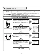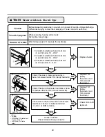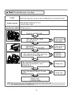
26
ᅐ
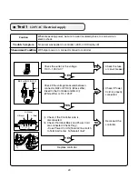
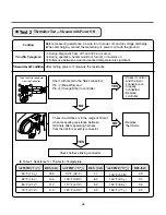
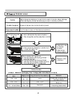
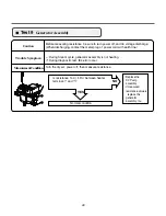
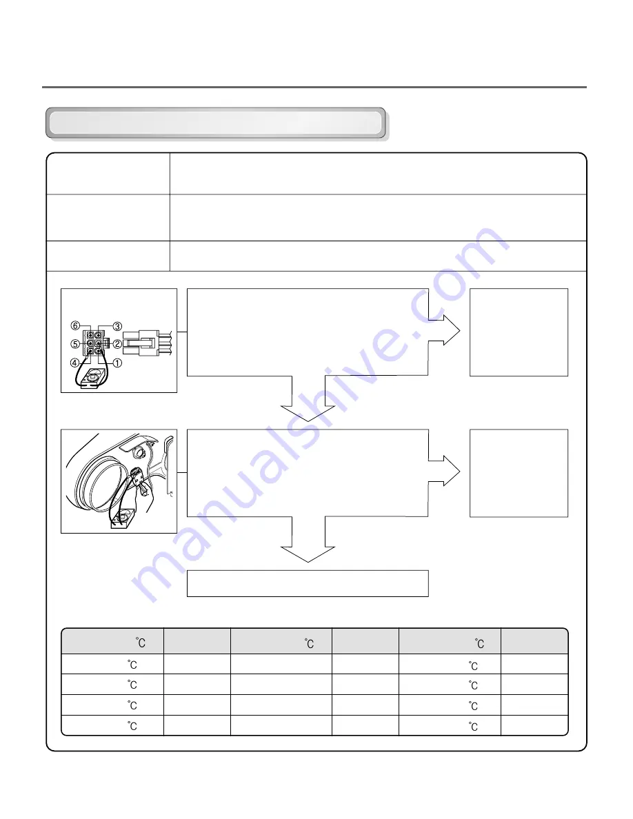
Test 2
Thermistor Test --- Measure with Power Off
Before measuring resistance, be sure to turn power off, and do voltage discharge.
(When discharging, contact the metal plug of power cord with the ground.)
၂
During Diagnostic Test, tE1 and tE2 error occur.
၃
During operation, heater would not turn off, or remains on.
၄
Difference between actual and sensed temperature is significant.
After turning power off, measure the resistance.
Short with metal to the NA6 connector’s
Pin
၂
(Blue Wire) and
Pin
၅
(Orange Wire) to controller.
• Check if control
and the 6 pin
connector are
properly
connected.
• Replace
controller
• Replace
thermistor.
Check if resistance is in the range of Table 1
when measuring resistance between
terminals after separating harness
from thermistor assembly connector.
Check harness-linking connector.
Take the NA6 Connector
from the Controller.
NO
NO
YES
YES
■
Table 1. Resistance for Thermistor Temperature.
Air TEMP.
[°F( )]
50°F (10
)
60°F (16
)
80°F (21
)
70°F (27
)
Air TEMP.
[°F( )]
90°F (32°C)
100°F (38°C)
110°F (43°C)
120°F (49°C)
RES.
[KΩ]
18.0
14.2
11.7
9.3
RES.
[KΩ]
7.7
6.2
5.2
4.3
RES.
[KΩ]
2.9
3.0
2.5
2.2
Air TEMP.
[°F( )]
130°F (54
)
140°F (60
)
150°F (66
)
160°F (71
)
Caution
Trouble Symptom
Measurement Condition


