background image

Summary of Contents for 79090102206

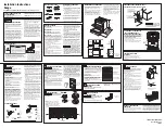
Page 1: ...h _ for cabinets above range top 36 _ I1 B m _ BACK VIEW Terminal Block FRONT VIEW RANGE C 24 24 DIMENSIONS A B 24 25 48 Maximum 45 Door Open 36 _ 1 8 30 MINIMUM CLEARANCE BETWEEN THE TOP OF THE COOKING SURFACE AND THE BOTTOM OF AN UNPROTECTED WOOD OR METAL CABINET OR 24 MINIMUM WHEN BOTTOM OF WOOD OR METAL CABINET iS PROTECTED BY NOT LESS THAN I 4 FLAME RETARDANT MiLLBOARD COVERED WiTH NOT LESSTH...

Page 2: ... be connected by means of a power supply cord Only a power supply cord kit rated at 40 amperes 125 250 volts minimum and marked for use with ranges shall be used Cord must have three 3 conductors Terminals on end of wires must be either closed loop or open end spade lugs with upturned ends Cord must have strain relief clamp NOTE MOBILE HOME iNSTALLATiON OR AREAS WHERE LOCAL CODES DO NOT PERMIT GRO...

Page 3: ...ting range Electrical failure or loss of electrical connection may occur GROUNDING INSTRUCTIONS A ground link is installed on this range which connects the center terminat of the terminal block neutral to the chassis The ground link is connected to the range by the center ground screw The ground link must not be removed unless national or local codes do not permit use of the ground link NOTE If th...

Page 4: ...ice has been installed to floor or wall Ensure the anti tip device is re engaged to floor or wall when the range is moved Do not operate the range without the anti tip device in place and engaged Failure to follow these instructions can result in death or serious burns to children and adults A Lacate the Bracket Using the Template Locate the bracket position by placing the template on the floor ag...

Page 5: ...the oven rack Take 2 readings with the spirit level placed diagonally take a reading in one direction and then in the other direction Level the range if necessary by adjusting the leveling legs Slide Anti Tip Bracket range back Range Leveling _ A _ i_ Leg x_ _ _L_ Anti Ti P _ Bracket To check if the anti tip bracket is installed properly use both arms and grasp the rear edge of range back Carefull...

Page 6: ......

Page 7: ... y la parte superior de Ja coclna i i_i ii ii Caja Terminal VISTA FRONTAL ESTUFA A C 24 24 24 A DIMENSIONES B 25 _ 36 1 8 3 _ k Puerfa ablerfa 45 UN MINIMO DE 30 DE ESPACIO ENTRE LA PARTESUPERIOR DE LA SUPERFICIE PARA ESTUFAR Y EL FONDO NO PROTEGIDO DE UN GABINETE DE METAL O MADERA O UN MINIMO DE 24 CUANDO EL FONDO DE METAL O MADERA DEL GABINETE ESTA PROTEGIDO POR NO MENOS DE I 4 DE MATERIAL RETAR...

Page 8: ...ENSIONES Este aparato puede ser conectado por medio de un cord6n de suministro de energ_a S6to debe usarse un juego de cord6n de suministro de energ_a tasado a 40 amperios 125 250 voltios coma minima y marcado para ser usado en estufas el6ctricas El cord6n debe tener tres 3 conductores Las terminates en los extremos de los atambres deben ser ya sea de lazo cerrado o de tal6n tipo espada de final a...

Page 9: ...ctor a tierra o tornillos de puesta tierra para poner ta unidad a tierra de acuerdo con los c6digos locales Conecte el neutral a la rama del circuito Para qultar la uni6n a tierra 1 Quite et tornitto de la uni6n a tierra usando un destornittador Phillips Guarde el tornilto para usa futuro 2 Doble la uni6n a tierra hacia arriba para que no entre en contacto con la estufa Tuerca _ hexagonal de 8 x 3...

Page 10: ...positivo antivuelco se haya reacoplado cuando mueva la estufa sobre el piso o a la pared No utiNce la estufa sin el dispositivo antivuelco instalado y acoptado Si no se siguen estas instrucciones se puede provocar la muerte o quemaduras graves en nihos y aduttos A Localice la Njaci6n usando el papeJ modelo LocaNce la posici6n de la fijaci6n colocando ta plantiNa en et piso pegada a la pared y la o...

Page 11: ...llas interior del homo Tome mfnimo 2 lecturas con el nivel coloque el nivel en diagonal para que ta cocina este nivelada de atr6s hacia adelante si es necesario ajuste las patas niveladoras nlvelador _ J_ o_b I_1 _ _ de anti __ incllnaci6n es u_a Paro verificor si la fijaciones de anti indinoci6n est6 instalado correctamente sostenga el borde trasero de la parte trasera de la estufa usando ambos b...

Page 12: ......

Reviews: