background image

Summary of Contents for 415.16661800

Page 1: ...ctive harm CAUTION Read and follow all Safety Statements Assembly Instructions and Use Care Directions before attempting to assemble and cook Some parts may contain sharp edges especially as noted in these instructions Wear protective gloves if necessary Parts Use and Care Assembly Troubleshooting Safety Rules Assembly Questions Call 1 800 241 7548 Parts Ordering Call 1 800 4 MY HOME To Installer ...

Page 2: ...Gas Code ANSI Z223 1 NFPA 54 Natural Gas and Propane Installation Code CSA B149 1 or Propane Storage and Handling Code B149 2 or the Standard for Recreational Vehicles ANSl A 119 2 NFPA1192 and CSA Z240 RV Series Recreational Vehicle Code as applicable AtI electrical accessories such as rotisserie must be electrically grounded in accordance with local codes or National Electrical Code ANSl NFPA 70...

Page 3: ...ull details call Sears Canada at 1 800 361 6665 Sears Installation Service For Sears professional installation of home appliances garage door openers water heaters and other major home items in the U S A or Canada caIt 1 800 4 MY HOME KENMORE ELITE FULLWARRANTY tf this grill fails due to a defect in material or workmanship within one year from the date of purchase call 1 800 4 MY HOME to arrange f...

Page 4: ...erclockwise by hand only do not use tools to disconnect Lift LP tank wire upward off of LPtank collar then tift LP tank up and off of support bracket install safety cap onto LP tank valve Always use cap and strap supplied with valve Failure to use safety cap as directed may result in serious personal injury and or property damage LPTankValve SafetyCap RetainerStrap A disconnected LP tank in storag...

Page 5: ...ed each time LP tank is exchanged or refilled Do not smoke during Ieak test Do not use an open flame to check for gas leaks Grill must be Ieak tested outdoors in a welI ventilated area away from ignition sources such as gas fired or electrical appliances During Ieak test keep grill away from open flames or sparks Use a clean paintbrush and a 50 50 mild soap and water solution Brush soapy solution ...

Page 6: ... cannot complete the connection disconnect regulator and repeat steps 5 and 6 If you are still unable to complete the connection do not use this regulator Do not insert any tooI or foreign objects into the valve outlet or safety fetid valve You may damage the valve and cause a leak Leaking propane may result in explosion fire severe personal injury or death If a leak is detected at any time STOP a...

Page 7: ...imum load for shelves is 10 Ibs Do not use a cooking pot larger than 9 on grid The grease tray must be installed into opening in back paneI and should be emptied after each use Do not remove grease tray until grill has compIeteIy cooled If you notice grease or other hot material dripping from grill onto valve hose or regulator turn off gas supply at once Determine the cause correct it then clean a...

Page 8: ... turn the burner control knob OFF wait 5 minutes for gas to clear and repeat the lighting procedure 8 464220008 Do not lean over grill while lighting 1 Turn OFF all gas burner control valves 2 OPEN lid during lighting 3 To ignite turn the rotisserie knob to_ and you wilt hear a clicking sound as the burner is being ignited 4 If ignition does NOT occur in 5 seconds turn the burner controls to OFF w...

Page 9: ... wire bristle brush Check inside the grill bottom for grease build up and clean often especially after cooking fatty meat Do not mistake brown or black accumulation of grease and smoke for paint Apply a strong solution of detergent and water or use a grill cleaner with scrub brush on insides of grill lid and bottom Rinse and allow to completely air dry Do not apply a caustic grill oven cleaner to ...

Page 10: ...ore in dry Iocation When LP tank is connected to grili store outdoors in weli ventilated space and out of reach of chiIdren Cover grill if stored outdoors Store griIl indoors ONLY if LP tank is turned off and disconnected removed from grill and stored outdoors When removing griIl from storage foItow CleaningBurner Assembly instructions before starting griIt Food Safety Food safety is a very import...

Page 11: ...is no direct flame to ignite the fats and juices that drip during cooking Indirect Cooking Instructions Always cook with the lid closed Due to weather conditions cooking times may vary During cold and windy conditions the temperature setting may need to be increased to insure sufficient cooking temperatures 1 Burner Cooking Cookwithdirector indirectheat Bestfor smallermealsorfoods Consumes lessfue...

Page 12: ...onModule 80007900 BatteryCap 80007380 MainBurner 80016303 ModuleCover 800t5536 Sideburner Wire 80017204 ControlKnob 80015534 Electrode AssywANire MainBurner 800t6705 Key Qty Descri tigtion Part 46 3 CarryoverTube 80015760 47 4 HeatDiffuser 80015759 48 I SwingAwayGrid 80015517 49 3 CookingGrate 80015518 50 t Rotisserie Burner FrontPaneI 80065115 51 t Rotisserie Burner RearPanel 80015734 52 t Electr...

Page 13: ...27 26 _34 70 37 _F 63 21 24 _50 t4 19 1 464220008 13 ...

Page 14: ...BottomShelf Attachthe twoLockingCastorsat tho roar of the bottomshelf Attachthe twoFixed Castorsat tho front Usothe providedCastorWrenchtofully tightencastors CasterWrench_ Fixed Caster 14 464220008 ...

Page 15: ...ovethe largeHEXNUTfromthe ElectronicIgnitionModule Placethe ModuleCoverover the ElectronicIgnitionModule Insertthisassemblyinto the holeof LeftCartSidePanel then usethe HEXNUTto securethe assembly to the panel A 67 66 1 4 20X Y2 Screw 1 4 Lock Washer QTY 6 QTY 6 Hex Module ElectronicIgnitionModut Holefor Electronic IgnitionModule LeftCart SidePanel RightCartSide Panel 464220008 15 ...

Page 16: ... rearof bottomshelf SecureLowerBackPanelto side panelsusingtwo 1f4 20x112 screwand1 4 lockwashersoneachside Securemiddleof LowerBackPanelto bottomshelfusingone 1 4 20xlf2 screwand1f4 lockwasher o T 66 67 1 4 Lock Washer 1f4 20X _ _ Screw QTY 5 QTY 5 16 464220008 ...

Page 17: ...ontocart Carduiiylowerthe ghliheadontothe cart atigningsiotsat bottomof grillheadwith postson cartsidepanels Grillheadmustface opensideof cart Be sureregulatorhoseandwiresare insidecart Beforeassembling the grill headonthe cart Afterassembling the grill headonthe cart 464220008 17 ...

Page 18: ...Brace InsertUpperDoorBraceundercontrolpaneIandbetweencart aides Secureusingtwo1 4 20xl 3 4 screwsand1f4 lock washersoneachside 0 66 1f4 Lock Washer QTY 4 7O 1 4 20X 1 3 4 Screw QTY 4 7 UpperDoorBrace 18 464220008 ...

Page 19: ...x14f4 screwand1 4 lockwasheroneachside A SecureCartUpperBackPanelto lowerbackpanelfrominside usingone1 4 20xlt2 screwand1t4 lockwasherin the centerhole B Donot fully tightenscrewsuntilsideshelfandsideburner installation is complete in later steps 0 66 1 4 LockWasher QTY 3 7O 67 1 4 20X 1 2 Screw QTY I 1t4 20X 14t4 Screw QTY 2 Upper Back Panel 464220008 19 ...

Page 20: ...ackpanel B Make suregreasetrayslideis alignedwithcutout in upperback panel C Attach FrontShieldTabsof TankHeatShieldunderUpper FrontBraceusingthree 8x3 8 self tapping screws D InstallGreaseTrayintoGreaseTraySlide E 63 8 X3t8 Self TappingScrew QTY 3 RearShieldTabs FrontShield Tabs wl Hole GreaseTray 20 464220008 ...

Page 21: ...into slotonfront of cartsidepanel Theninsertbottomhingetab intobottom slotonfrontof cartside panelmakingsure middlehingetab alsoinsertsintothe middleslot Secureeachdoorto cartsidepanelusingfour 8 32x3f8 flat headscrews 1 76 8 X 318 FlatHeadScrew QTY 8 464220008o21 ...

Page 22: ...oughbracket Seeviews B C and D Makesurethe tabsinthe middleof side shelfareinsertedintothe sidepanelcut outs C Attachone1 4 20xl 3t4 screwand 1f4 lockwasherat the rearshelfsupportbracket D Attachtwo114 20x518 screwand1f4 lockwasherat the frontshelfsupportbracket E Nowfullytightenscrewsat the topsof the shelfsupportbrackets B For left sideburner shelf repeat abovestepsforB C D E Fullytightenrearpan...

Page 23: ...acketbeneathsideburnershelf fasciaso thatvalvestemcomesthroughlargercenterholein fascia B AttachBezelto Fasciausingscrewsthatwere removed frombracket B PressControlKnobontovalvestern B ValveStem Fascia outlined for clarityof view 0 71 8 LockWasher QTY 2 Remove T 72 8X 318 Screw QTY 2 Sideburner Shelf Control Knob Bezel Fascia 464220008 23 ...

Page 24: ...Sidebumertubealignscorrectlyontosideburnervalve underneathleft shelf B SecureSidebumerto panusingtwo 10 24x3 8 screwsand5mm fiberwashersand 10lockwashers C AttachSideburner IgniterWire fromElectronicIgnitionModuleto Electrode Tip underneathleftshelfshown D O 73 74 O 75 10 LockWasher 10 24X 318 Screw 5mmFiberWasher QTY 2 QTY 2 QTY 2 Sideburner 24 464220008 Sideburnerlgniter Wire ...

Page 25: ...screws 8tock washers and 8flangenutsto shelf A PlaceBurnerCapontosideburnerandattachSidebumerCap alp C PtaceSidebumerGrateontosidebumershelf PlaceGriddle ontosidebumershelf 68 O 71 8 LockWasher QTY 4 68 8Hex Nut QTY 4 T 72 8X 3 8 Screw QTY 4 34 Sideburner CapClip QTY I SidebumerGrate BurnerC_ 464220008 25 ...

Page 26: ...s InstalleachHeatDiffuserby insertingoneendwithperforated hole stampingwith FRONT intoslots at frontoffirebox bracketandrestingoppositeend Stamping with REAR onpin locatedat backoffirebox HeatDiffuser 26 464220008 ...

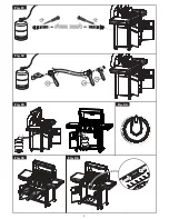
Page 27: ...n the upposition Grid Grate WiringConnections andBattery Connecteachof thewiresfromthe mainburnerelectrodes rotisserieburnerelectrode and sidebumerelectrodeintothe backof the ElectronicIgnitionModule Total 6 connections Connectthetwowiresfromthe switchwiringharnessinto the backof the ElectronicIgnitionModule Total 2 connections NOTE Switch terminals are larger than electrodeterminals and should on...

Page 28: ...ill Securetankwithtankscrewunderbottomshelf SeeUse Care section of this manualto perform the Burner FlameCheck andfor important safety instructions before using Ldator ICAUTIONI LPTank valve must face to front of cart once tank is attached Failure to installtank correctly may allow gas hose to be damaged in operation resulting in the risk of fire Alwayskeep LPtankin upright position during use tra...

Page 29: ...ace Burner s will not light usingignitor Continued onnext page Toomuchgreasebuildupinburnerarea GASISSUES Burnernot engaged with controlvalve Obstruction in burner No gasflow Vaportockat couplingnut to LPtank Couplingnut andLP tankvalvenot fully connected ELECTRICAL ISSUES Electrode crackedor broken sparksat crack Electrode tip not inproperposition Wireand orelectrodecoveredwith cookingresidue Wir...

Page 30: ...tgrill Turn offknobsandLPtankvalve Disconnect couplingnutfrom tank Reconnect andretry Turnfrontof griIito facewindor increaseflameheight RefiIi LPtank Referto Suddendropin gasflow above Flare up Greasebuildup Cleanburnersandinsided grill firebox Excessive fat in meat Trimfat frommeatbeforegrilling Excessive cookingtemperature Adjust lower temperature accordingly Persistent greasefire Greasetrapped...

Page 31: ...rcingto grillaway fromburner s Weakbattery Electrodesarewet Electrodescrackedor broken sparksat crack withnewbatteryandgood wireconnections moduleis faulty Areoutputconnections on andtight Arethe electrodetips pointingin theright direction Is thegaptoo big Areoutputconnections on andtight If possible observegrillin darklocation Operate ignitionsystemandlookfor arcingbetweenoutputwires andgrillfram...

Page 32: ...ems like vacuums lawn equipment and electronics call or go on line for the location of your nearest Sears Parts Repair Service Center 1 800 488 1222 U S A 1 800 469 4663 Canada Call anytime day or night www sears com www sears ca To purchase a protection agreement on a product serviced by Sears t 800 827 6655 U S A t 800 361 6665 Canada Para pedir servicio de reparaci6n a domicilio y para ordenar ...

Reviews: