Kemppi A3 MIG Operating Manual Download Page 20

20

A3 MIG Welder

© Kemppi Oy 2018

1826

OPERA

TING M

ANU

AL

4.7  Welding and system setup

Quick setup

To set the values of the functional parameters for MIG features, use the QUICK SETUP 

feature, which you can activate by briefly pressing the SETUP button (5).

Select the parameter to adjust using the left-hand side control knob or the button (8) 

and then set the parameter value with the right-hand side control knob. The value you 

specified is instantly stored in the control panel memory. The following tables list the 

parameter values that can be specified for the MIG features.
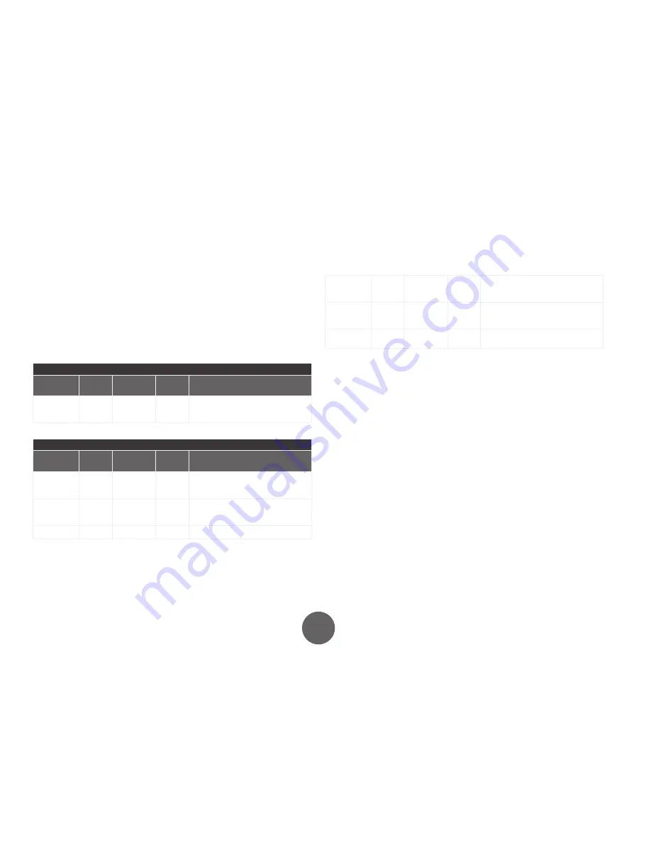
QUICK SETUP, MIG
Parameter

Display

Value range Factory 

setting

Description

Creep start 

level

Cre

10 ... 170 %

50 %

Percent of wire feed speed default

10% refers to slow start,

170% refers to fast start

QUICK SETUP, 1-MIG, WiseThin, WiseRoot
Parameter

Display

Value range Factory 

setting

Description

Creep start 

level

Cre

10 ... 170 %

50 %

Percent of wire feed speed default

10% refers to slow start,

170% refers to fast start

Hot start 

level

Hot

-50 ... 75 %

30 %

Percent of welding power:

-50% refers to cold start

+75% refers to hot start

Hot start time

H2t

0 ... 9.9 s

1.2 s

The duration of the hot start in seconds.

Crater fill 

start level

CrS

Crater fill 

end level ... 

250 %

90 %

The welding power at the beginning of 

the crater fill stage as a percentage of 

the welding power pre-set value.

Crater fill end 

level

CrL

10 ... Crater 

fill start level

30 %

The welding power at the end of the 

crater fill stage as a percentage of the 

welding power pre-set value.

Crater fill 

time

Crt

0 ... 9.9 s

2 s

The duration of the crater fill stage in 

seconds.

All setup parameters

The machine has several parameters, whose settings can be specified with the control 

panel's SETUP function as follows:

1.  Press and hold down the SETUP button (5) for at least 5 seconds. 
2.  Select the parameter to adjust using the left-hand side control knob. The parameter 

name is shown in display left-hand display. 

3.  Specify the parameter value with the right-hand side control knob. The selected 

value is shown in the right-hand display. The parameter’s value is immediately 
stored in the memory. 

4.  Exit the SETUP mode by pressing and holding down the SETUP button again for at 

least 5 seconds or by briefly pressing the ESC button. 

All welding processes have their own setup parameters. For example, adjusting the post-

current for synergic MIG welding does not affect the post-current of normal MIG weld-

ing.

The tables below show the features available in this welding machine and their possible 

values.

Summary of Contents for A3 MIG

Page 1: ...1920860 1826 A7 MIG Welder A3 MIG Welder EN OPERATING MANUAL...

Page 2: ...3 Standard MIG features 14 4 4 Optional MIG features 15 4 5 Memory channels 16 4 6 Synergic 1 MIG WiseThin and WiseRoot welding 17 4 7 Welding and system setup 20 4 8 Touch sensor seam search 23 4 9 C...

Page 3: ...Kemppi web site at www kemppi com The specifications presented in this manual are subject to change without prior notice Important notes Items in the manual that require attention in order to minimiz...

Page 4: ...luded in the system are suitable for both indoor and outdoor use Always make sure that the air flow to the machine is unrestricted The recommended operating temperature range is 20 40 C Positioning th...

Page 5: ...nt and rear 1 Control panel 2 Main switch 3 Main power indicator light ON OFF 4 Overheating indicator 5 System configuration DIP switches 6 Control cable connection 7 Welding cable connection negative...

Page 6: ...e buttons and knobs are used for adjusting functions The displays and indicators reflect the operating modes of the machine 1 7 6 5 8 4 3 9 2 Figure 3 4 Control panel layout 1 Miscellaneous functions...

Page 7: ...es in the power source Panel P1 DeviceNet configuration 1 2 Baud rate 125 500 kbps 3 8 Mac ID 0 63 Panel P2 System configuration 1 2 Touch sensor voltage 50 200 V 3 Safety stop OFF ON 4 Collision sens...

Page 8: ...button 3 Euro connector 4 Wire feeder control cable connector 5 Wire liner connector 6 Welding cable connector 7 Gas inlet A3 Wire Feeder 25 Power connector 1 2 3 4 5 6 7 Figure 4 10 Wire feeder with...

Page 9: ...he wire end and cut off any deformed section before pulling it out from the wire feeder Straighten about 20 cm of the new filler wire and ensure the tip has no sharp edges File if necessary as a sharp...

Page 10: ...shaft fits in the cut on the feed roll DuraTorque 400 4 wheel wire feed mechanism accessories Wire guide tubes mm outlet tube middle tube inlet tube Ss Al Fe Mc Fc plastic 0 6 SP007437 SP007429 SP0072...

Page 11: ...rated duty cycle The cooling fan continues to cool the machine down When the light goes off the machine is ready to weld again Cooling fans The A3 Power Source incorporates two simultaneously operati...

Page 12: ...lso used for specifying the oper ating parameters A parameter for adjustment is selected with the left hand knob while the value of the parameter is selected with the right hand knob Adjusting MIG dyn...

Page 13: ...weld data feature To use the feature press but tons 3 and 4 simultaneously Selecting the welding process The welding process selection button 7 allows you to se lect the welding process you want to u...

Page 14: ...he synergic 1 MIG welding Hot start Hot The purpose of hot start is to reduce start faults for ex ample when welding aluminium or other materials with particularly good thermal conductivity In this sc...

Page 15: ...eft hand side reads 1 1 enter the first value of the activation code using the right hand side control knob The value you have entered is shown in the right hand side display 5 Select the entry of the...

Page 16: ...mory channel you want using the CH button 10 3 Specify the welding settings you want and store the selections by pressing SAVE button 11 4 Press the MEMORY button 9 twice The ON indicator light will t...

Page 17: ...activate program selection and the control panel displays start flashing 4 Select the material group with the left hand side control knob and the welding program for the material group with the right...

Page 18: ...Ar 2 CO 231 0 8 SS 309 Ar 30 He 1 O 232 0 9 SS 309 Ar 30 He 1 O 233 1 0 SS 309 Ar 30 He 1 O 234 1 2 SS 309 Ar 30 He 1 O 242 0 9 FC 316 Ar 18 25 CO 244 1 2 FC 316 Ar 18 25 CO 252 0 9 FC 316 CO 254 1 2...

Page 19: ...0 9 SS 316 Ar 2 CO 723 1 0 SS 316 Ar 2 CO 724 1 2 SS 316 Ar 2 CO WiseThin SPE group Program number Wire mm Material Shielding gas 743 1 0 CuSi 3 Ar 753 1 0 CuAl 8 Ar WiseRoot Fe group Program number W...

Page 20: ...seconds Crater fill start level CrS Crater fill end level 250 90 The welding power at the beginning of the crater fill stage as a percentage of the welding power pre set value Crater fill end level Cr...

Page 21: ...the beginning of the crater fill stage as a percentage of the welding power pre set value Crater fill end level CrL 10 Crater fill start level 30 The welding power at the end of the crater fill stage...

Page 22: ...in the beginning of the WiseRoot WiseThin welding WiseFusion parameters Parameter Display Value range Factory setting Description WiseFusion on fus off Off on On na N A Off Switch WiseFusion on off on...

Page 23: ...le The target for the positive pole can be changed by a user A relay in the touch sensor device enables the configuration by a DIP switch The touch sensor system consists of hardware and soft ware The...

Page 24: ...drops down under the 113 V level when loaded by a 5 6 k resistor which is the nominal DC resistance of the human body In some cases voltage levels above 113 V can still cause minor harm such as pain...

Page 25: ...ed to the ro bot by the welding system In addition a collision causes always the Error 146 Collision detected in the welding system When the error occurs the power source stops welding immediately Fie...

Page 26: ...heck shielding gas supply Check and set gas flow rate Check gas type for application Check gun electrode polarity Check correct welding program selected Check correct channel number selected on wire f...

Page 27: ...failure or shutdown Welding is interrupted when a lost connection is detected Check the fieldbus cable If the robot has been shut down turn the robot on Switch off and restart the power source 133 SAF...

Page 28: ...he machine pro vides protection for auxiliary devices Use the same type and rating of fuse as marked beside the fuse adapter Damage caused by incorrect fuse selec tion is not covered by the guarantee...

Page 29: ...mains socket and wait about 2 minutes capacitor charge before removing the cover plate Check at least every half year the electric connectors of the machine clean any oxidized parts and tighten loose...

Page 30: ...a regional collection center as per the instructions of local authorities or a Kemppi repre sentative By applying this European Directive you will improve the environment and human health 9 ORDERING...

Page 31: ...iary device supply Supply voltage 50 V DC Fuse 6 3 A delayed Environmental characteristics dimensions and classification Operating temperature range 20 C 40 C Storage temperature range 40 C 60 C Exter...

Page 32: ...kl ringer Konformit tserkl rungen Declaraciones de conformidad Vaatimustenmukaisuusvakuutuksia D clarations de conformit Dichiarazioni di conformit Verklaringen van overeenstemming Samsvarserkl ringer...

Reviews: