X-band 12kW Upmast Magnetron Transceiver
Chapter 7: CONNECTION DETAILS
HBK-2300-3 Issue 2
Page 25 of 40
7 CONNECTION DETAILS
7.1
Transceiver
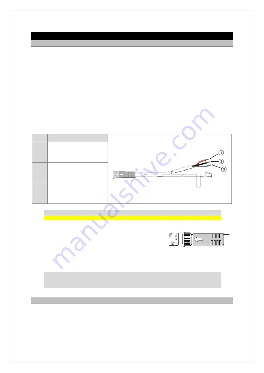
STANDARD CABLE
Cable part number
A55079
(25m length) connects the transceiver to the managed network switch and
the DC power supply. The cable contains both DC power and the LAN data wires.
All power connections must be made via the E70352 power supply as this controls and monitors
the DC supply to the system. The transceiver must not be directly connected to a separate DC
supply.
Each system requires a dedicated E70352 unit.
The power connection between the transceiver and the E70352 must be via the specified power
and cable (purchased separately).
The transceiver must be connected to the POWER OUT terminals of the E70352.
The screen (drain) strands of the cable must be connected to one of the E70352 SCREEN
terminals.
Item
Description
1
RED WIRE
Connect to the positive
POWER OUT terminal of
the E70352.
2
BLACK WIRE
Connect to the negative
POWER OUT terminal of
the E70352.
3
SCREEN STRANDS
Connect to one of the
SCREEN terminals of the
E70352.
CAUTION
The standard cable must not be cut, shortened or lengthened.
TRANSCEIVER CONNECTOR
The power and data connector is at the rear of the radar scanner
unit.
Ensuring that the arrow on the power and data cable connector is aligned with the red triangular mark
on the radar scanner connector,
connect the cable to the scanners’ connector, and fully hand
-tighten.
Do NOT use a wrench or any other tool.
NOTICE
If the antenna connector is disconnected after initial installation, it is recommended that before
reconnecting, you lightly coat the connector thread with Renolit Aqua 2 Calcium grease.
7.2
Longer LAN cable
Where the distance between the network switch and the display sub-system exceeds 25m, a
screened CAT5e LAN cable must be used and connected to the existing cable. Where cables are
joined a screened coupler must be used and the joint should be secured to ensure that the connection
cannot work loose.


